D
IRECTION 5771498-100, REVISION 6 VENUE™ SERVICE MANUAL
Chapter 3 - System Setup 3-21
PRELIMINARY
3-4-3-4 Peripheral/Accessory Interface Panel
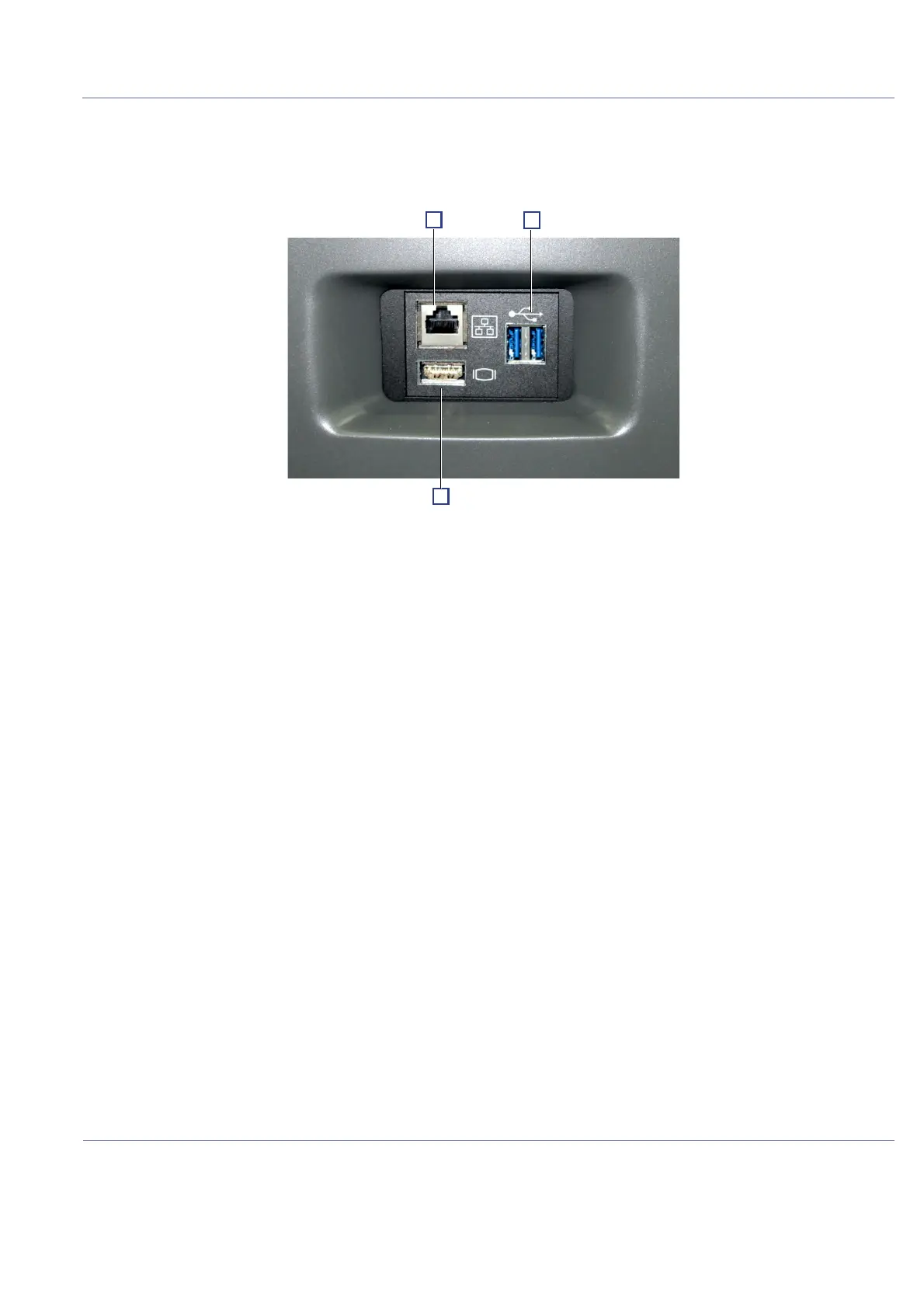
Figure 3-24 shows a view of the Venue™ ultrasound unit rear panel showing external peripheral/
accessory connectors.
1 Ethernet LAN connector — 1000 Base-TX Ethernet IEEE 802.3 (3kV insulation)
2 Dual USB 3.0 connector (not insulated)
3 HDMI connector (not insulated)
3-4-4 EMI Protection
The Venue™ has been designed to minimize the effects of Electro-Magnetic Interference (EMI). Many
of the covers, shields, and screws are provided primarily to protect the Venue™ from image artifacts
caused by this interference. For this reason, it is imperative that all covers and hardware are installed
and secured before the Venue™ is put into operation.
See EMI Limitations on page 2 - 4 for more information about EMI protection.
Figure 3-24 View of the Venue™ Peripheral/Accessory Interface Panel

 Loading...


