Chapter 8 - Replacement Procedures 8-123
D
IRECTION 5771498-100, REVISION 6 VENUE™ SERVICE MANUAL
PRELIMINARY
8-7-3 BE to Cockpit Cable Replacement Procedure
8-7-3-1 Tools
• Appropriate Phillips screwdriver
• Flat screwdriver
• 2.5 mm Allen key.
8-7-3-2 Time Required
15 min
8-7-3-3 Preparations
1.) Shut down the Venue™ ultrasound unit, as described in Power Shut Down .
2.) Make sure the On/Off power switch is set to Off.
3.) Make sure the system is standing securely on a level surface, with the wheels in the locked position.
8-7-3-4 BE to Cockpit Cable Removal Procedure
1.) Remove all accessories.
2.) Remove the following covers: RS Probe, Lower Front eTower, Left side eTower, Right Side eTower,
Riser Thermal, and MPB Door cover,
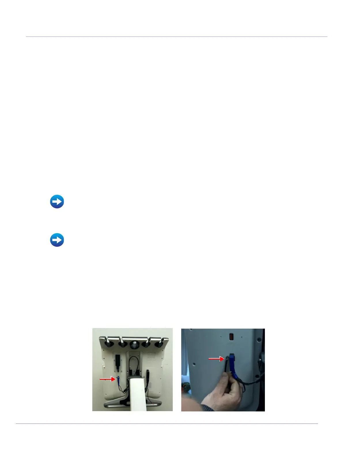
3.) Disconnect the BE TO COCKPIT CABLE from the monitor:
• Disconnect the cable connector (use flat-head screwdriver)
• Release Ground cable (use Phillips screwdriver).
Refer to Table 9-14 on page 9-14.
• Accessories - Replacement Procedures
• RS Probe Cover Removal Procedure
• Lower Front eTower Cover Removal Procedure
• Left Side eTower Cover Removal Procedure
• Right Side eTower Cover Removal Procedure
• Riser Thermal Cover Removal Procedure
• MPB Front Metal Door Removal Procedure
Figure 8-116 Cockpit (Monitor) Cable and Cockpit Ground Cables Removal

 Loading...


