8-146 Section 8-6 - Mechanical Parts- Replacement Procedures
D
IRECTION 5771498-100, REVISION 6 VENUE™ SERVICE MANUAL
PRELIMINARY
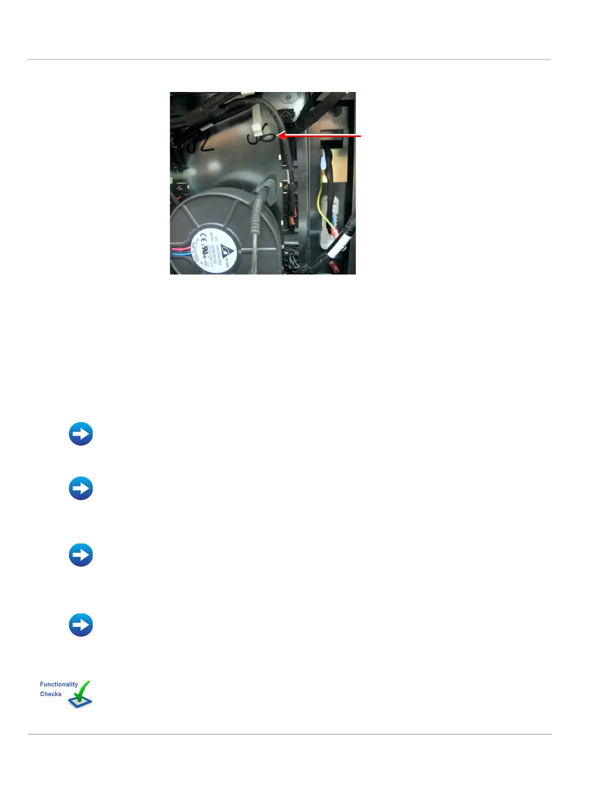
8.) Slide up and disconnect the other side of the MPB to BIB Control Cable from the J6 connector.
9.) Remove the MPB to BIB Control cable.
8-7-8-5 MPB to BIB Control Cable Installation Procedure
1.) Connect one side of the MPB to BIB Control Cable to the J6 connector. Make sure the arrow on the
cable connector is facing up.
2.) Connect the other side of the MPB to BIB Control Cable to the blower cable connector.
3.) Secure the cable with plastic clips.
4.) Install the MPB module.
5) Install the MPB Front Metal Door.
6.) Install the following covers: Lower Front eTower, Left side eTower, Right Side eTower and RS
Probe cover.
7.) Install all accessories.
8.) Turn ON power to the system.
Figure 8-148 Disconnecting MPB to BIB Control Cable from J6 Connector
• MPB Module Installation Procedure
• MPB Front Metal Door Installation Procedure
• Left Side eTower Cover Installation Procedure
• Right Side eTower Cover Installation Procedure
• Lower Front eTower Cover Installation Procedure
• Accessories - Replacement Procedures
Perform the checks listed in MPB to BIB Control Cable Replacement Procedure on page 8-218

 Loading...


