186 ADV200 • Quick start up guide
A 1.4 Jumpers and Switches
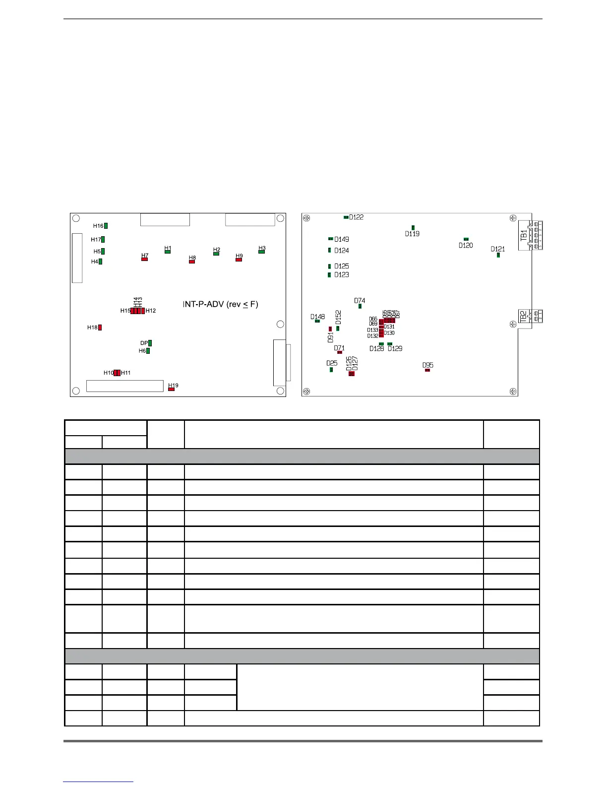
INT-P-ADV (MASTER and SLAVE) cards
The jumpers and switches on these cards are factory-set. DO NOT change these
settings.
A 1.5 LEDs
The cards incorporate a LED diagnostics system for rapid analysis of everything
happening on a multi-unit drive.
INT-P-ADV (MASTER and SLAVE) cards
INT-P-ADV (≥ Rev L)
LEDS
Colour FUNCTION
Normal
functioning
≤ F (*) ≥ L (*)
MONITOR
H1 D119 Green +15V�PWR�U monitor On
H2 D120 Green +15V�PWR�V monitor On
H3 D121 Green +15V�PWR�W monitor On
H4 D123 Green +15V monitor On
H5 D125 Green -15V monitor On
H6 D129 Green +3,3V monitor On
D25 Green +3,3V R monitor On
H16 D122 Green +24V monitor On
H17 D124 Green +5V monitor On
DP* D128 Green
It switches on after power supply start-up when the FPGA configuration
sequence is complete
On
D149 Green +5V safety monitor On
ALARM
H7 D67/D64 Red PHASE U
They light up to indicate a short circuit between the output
phases
Off
H8 D68/D65 Red PHASE V Off
H9 D69/D66 Red PHASE W Off
H10 D126 Red It lights up to indicate a power rectifier heat sink overtemperature Off

 Loading...


