ADV200 • Quick start up guide 45
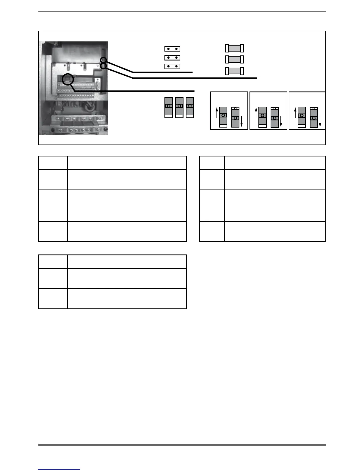
5.2.4 Switches, jumpers and LED
LEDs :
S1 S2 S3
PWM
RUN
PWR
Switches :
S1
Jumpers :
HC0
HC1
CFG
V I
S2
V I
S3
V I
Switch V/I settings on inputs and analog output LEDs Function
S1
Analog input 1
Default = voltage (±10 V)
PWM
(green)
LED lit during IGBT modulation
S2
Analog input 2
Default = voltage (
±10 V)
RUN
(green)
Flashes (freq. 1 sec) if no errors or faults
have occurred.
If ON or OFF, indicates an error conditions
(software hangup)
S3
Analog output 2
Default = voltage (
±10 V)
PWR
(green)
ON when the regulation card is correctly
powered
Jumpers Function
HC0
HC1
Reserved. Deafult = Open
CFG (1)
Open = 400 Vac rated voltage (default) (2)
Closed = 460 Vac rated voltage (3)
(1) Need to be veried the setting of the Unvervoltage alarm threshold
For drive size 7 and parallel units, Threshold can be selected thru S1 switch (mounted on R-PSM
board). This selection has to be the same of parameter PAR 560.
(2) Drive is automatically set for EU conguration (400V/50Hz). Parameter 460 will show 0 : EU (default
conguration).
(3) Drive is automatically set for USA conguration (460V/60Hz). Parameter 460 will show 1 : USA.