ADV200 • Quick start up guide 49
Table 5.2.5.1: TB1 terminal strip on R-PSM
Terminal Designation Function Electrical specifications
23 ENABLE
ENABLE digital input of the pre-charge
control
5mA @ +24Vdc (+20% max, -20% min)
52 ENABLE in COM ENABLE common digital input
32 Digital Out 1 Drive OK 24V / 20mA typ (40mA max)
33 Dig Out Com Common Digital Out 1 and Digital Out 2 -
34 0V24 Out Reference point for power supply -
35 +24V Out Power supply output 150mA resettable fuse
36 Digital Out 2 Digital output : Factory preset as Mains Loss 24V / 20mA typ (40mA max)
37 Dig Out Supply Power supply for digital outputs -
70, 72 Relay 1 Factory preset as Precharge OK 250Vac - 30Vdc - 0,5A
Terminal strip TB1
Cable Cross Section (flexible conductor) Recommended stripping
Tightening torque (min)
(mm
2
) AWG (mm) (Nm)
0,2 ... 2,5 24 ... 12 7 0,5
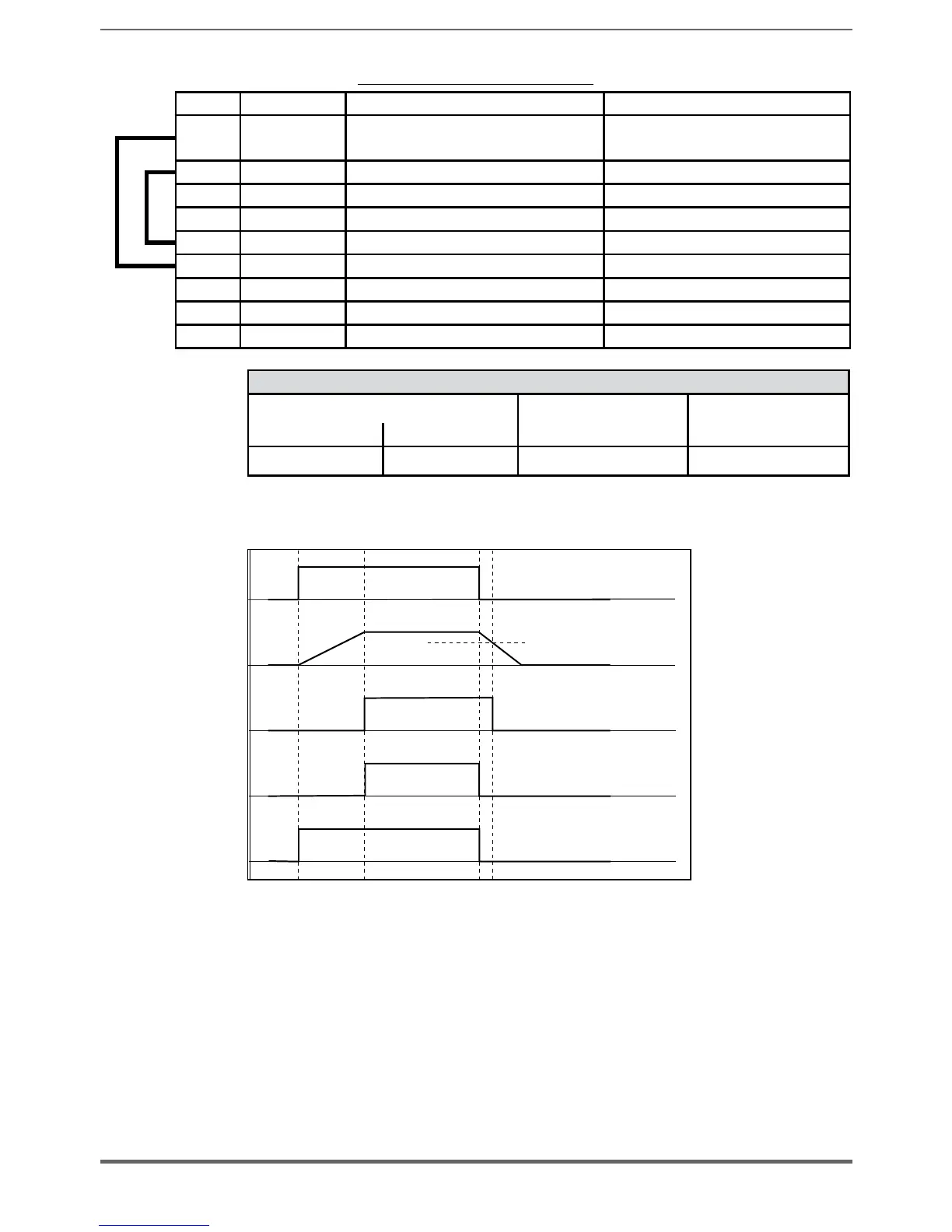
5.2.5.2 Behavior of Pre-charge OK Relay-Digital Out 1, Digital Out 2 at
“PowerOn” and “PowerOff”
Undervoltage
DC
AC Power Supply
DC Voltage
Precharge OK Relay
Digital Out 1 - Drive OK
( Default configuration )
Relay 1 – Precharge OK (factory setting)
The relay between terminals 70 – 72 closes at the end of the pre-charge phase
and opens when DC voltage drops below the DC Undervoltage threshold. Wiring
of the OK relay contact (70 - 72) in series with the Enable chain of the ADV200
regulation card is recommended
Digital Out 1 – Drive OK
Digital output 1 connected to terminal 32 goes high at the end of the pre-charge
phase and goes low under one of the following conditions:
• power failure
• lack of a power supply phase

 Loading...


