ADV200 • Quick start up guide 53
Note! For the position of the Jumpers, see “Figure 5.2.5.1: Position of Switches, LEDs and Jumpers on
R-PSM card” .
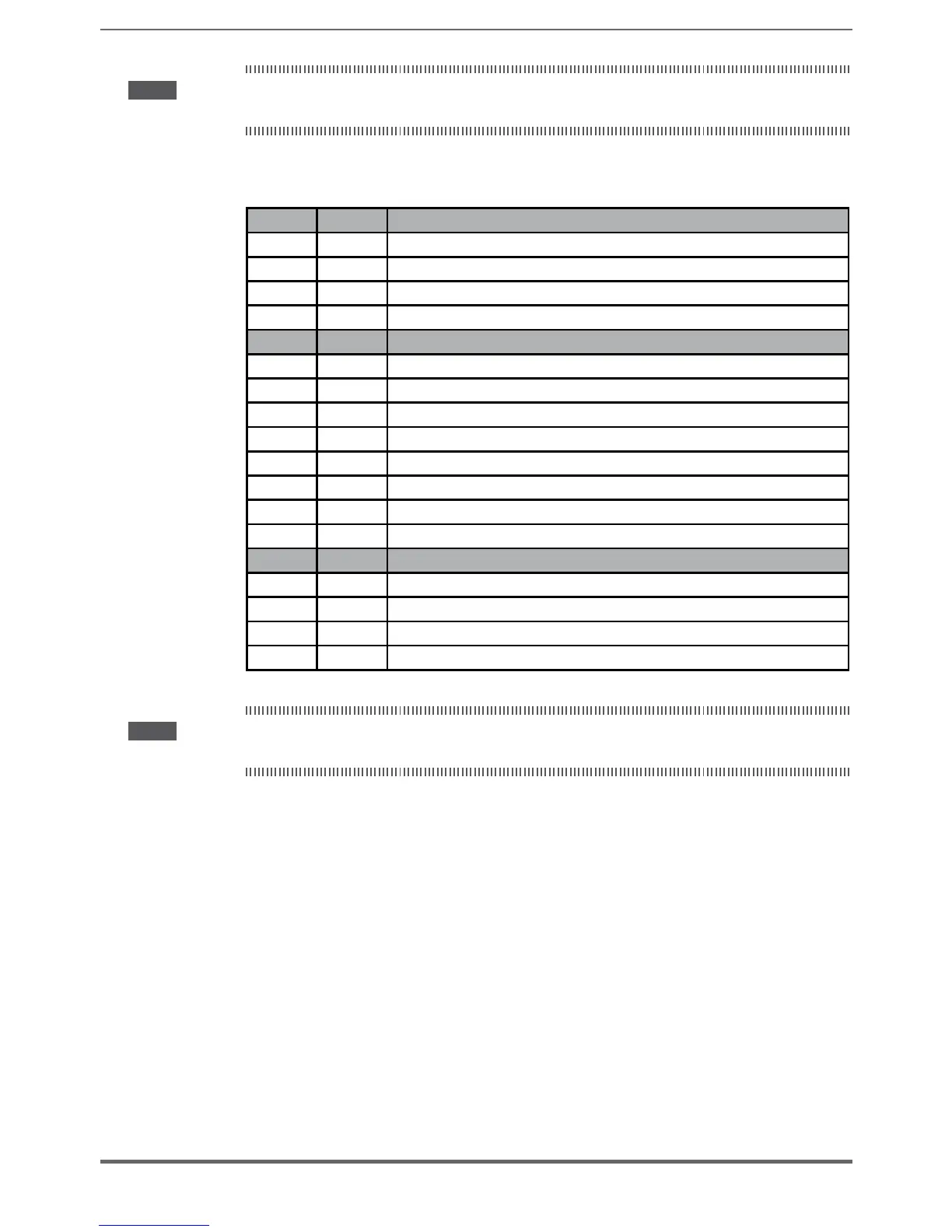
5.2.5.5 Leds on R-PSM card
LED Color “MONITOR” function
D9 GREEN +3V3 logic power
D78 GREEN +5V logic power
D79 GREEN +22V driver power
D91 BLUE Presence of DC-Link voltage
LED Colore “SIGNAL” function
D1 GREEN DC-Link voltage above UNDERVOLTAGE limit
D2 GREEN Power supply enabled
D3 GREEN Not used
D4 GREEN Power supply OK (no alarms – excluding UV)
D6 RED Phase loss or Main loss alarm
D7 RED Heatsink overtemperature alarm
D8 GREEN FPGA configuration in progress
D84 RED Wrong line frequency alarm
LED Color “POWER SUPPLY STATE” functions
D83 YELLOW Bit S0: codes STATE of power supply (LSB)
D80 YELLOW Bit S1: codes STATE of power supply
D81 YELLOW Bit S2: codes STATE of power supply (MSB)
D82 YELLOW SCR bridge enabled
Note! For the position of the Jumpers, see “Figure 5.2.5.1: Position of Switches, LEDs and Jumpers on
R-PSM card” .

 Loading...


