XNX Universal Transmitter
Section 3 - Calibration
102
Zero and Span Calibration for EC/mV Sensors and
Searchpoint Optima
Caution: Before initial calibration, allow the sensor to stabilize for 30 minutes after applying power.
When in zero and span calibration modes, the current output from the sensor is inhibited (default
2mA) to avoid false alarms.
For sticky gases (HCI, HF, CI
2
, CIO
2
, HCN, F
2
and O
3
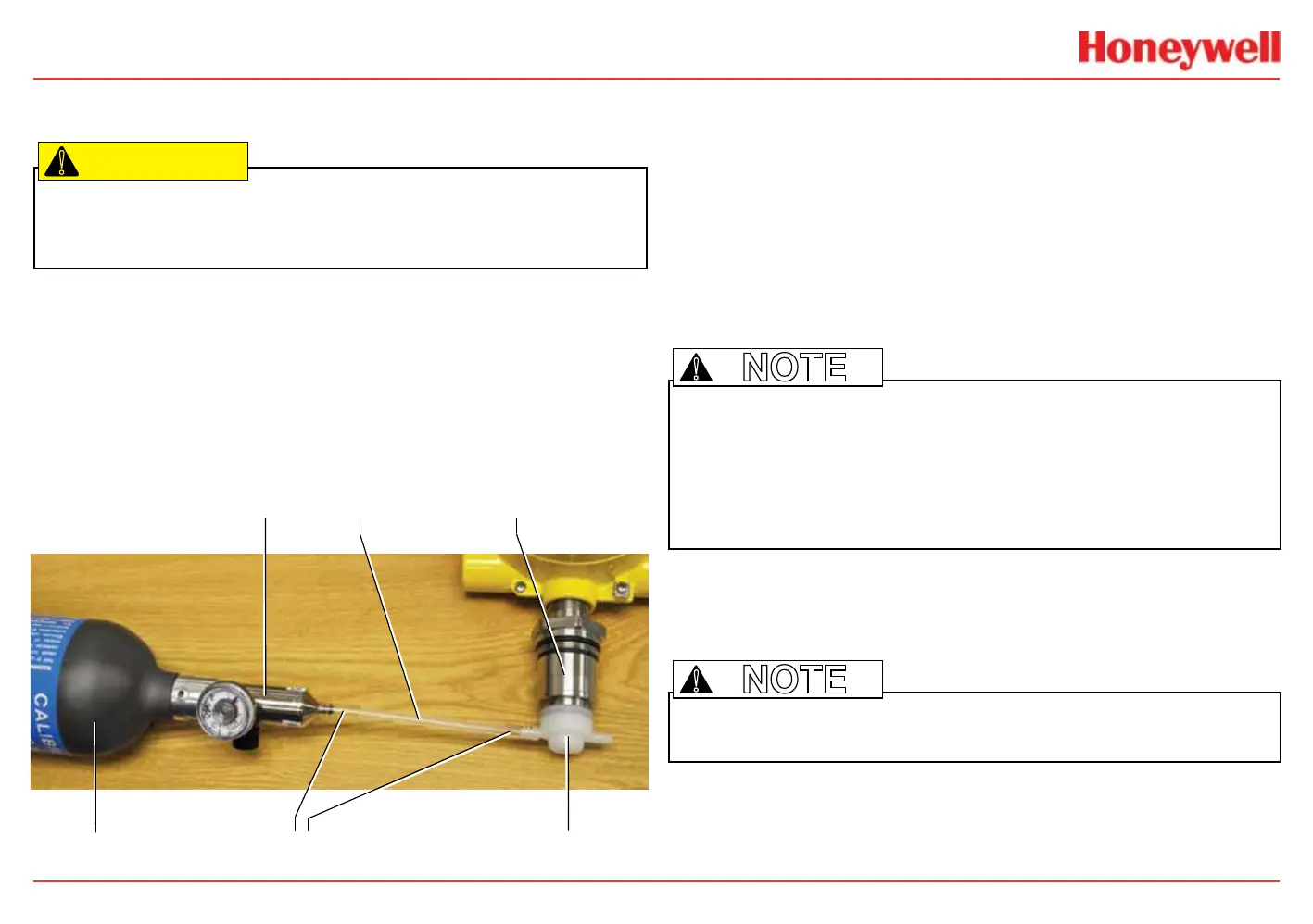
), use PTFE tubing
with short pieces of Tygon tube for the nal connection (due to the
inexibility of PTFE). This minimizes adhesion of the gas to the tube
surface and allows more accurate measurement. Use a one-inch section
of Tygon tubing as a union sleeve to join the calibration cup’s tting and
the PTFE tubing. Push the PTFE tubing against the tting so they make
secure contact as shown in the illustration. Gas should not be able to
contact the Tygon sleeve. Attach the PTFE tubing to the regulator in the
same manner.
PTFE (Teon) tubing
calibration cupcalibration gas
stainless steel regulator EC sensor
Tygon sleeves
Figure 192. Joining the PTFE tubing with Tygon tubing
To calibrate the sensor, use an appropriate span gas cylinder, tubing,
magnet, and calibration gas ow housing. Set the ow regulator to 300-
375 ml/min for XNX EC sensors or 300-700 ml/min for XNX mV sensors.
Use a compressed gas cylinder (20.9%Vol oxygen) to perform the zero
calibration if the sensor is located in an area containing any residual
amount of the target gas. If no residual gas is present, background
air can be used to perform the zero calibration. Contact a Honeywell
Analytics representative for details about suitable calibration kits. To
calibrate the sensor, follow the steps in Calibration Procedure.
Note: The oxygen sensor does not require a zeroing procedure. Background air (20.9%Vol oxygen)
can be used to span the oxygen sensor in place of a compressed air cylinder (20.9%Vol oxygen). See
the Sensor Data section for other sensors.
Note: EN performance standards require 10 minutes stabilization time for application of zero and span
gas for performance-approved EC, mV, and IR sensors prior to calibration.
!
Calibration Procedure
This section outlines the steps for calibrating the transmitter’s attached
sensors.
Note: Perform the zero calibration before the span calibration.
1. If using a compressed gas cylinder, push the calibration gas
ow housing onto the bottom of the sensor and apply the gas.
2. Access the Gas Calibration Menu. This menu is for both zero
and span calibrations.
 Loading...


