XNX Universal Transmitter
Installation and Operation
47
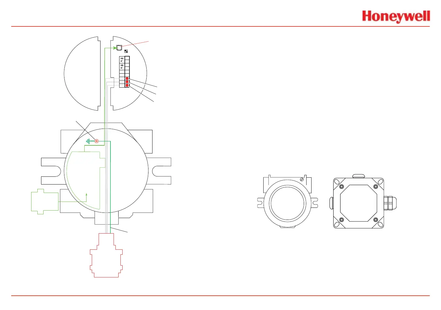
Local HART
IS Barrier
(optional)
HART
Adaptor
4
3
2
1
Ref
+
9
8
7
6
5
J1 HART
S1 S2
Terminal Block 1
Com
Sense
-
Optional Local HART
IS Barrier must
be connected to J1
Ground Wire from
Sensepoint PPM and HT
Internal Ground Lug
MPD
705
Sensepoint
Sense 7
Com 8
Ref 9
Figure 44. mV personality wiring
mV Remote Sensor Mounting
The sensor can be mounted remotely from the transmitter; the
installation will vary by installed location, sensor and thread type
used. To remotely mount the sensor, follow this procedure:
1. Install a junction box appropriately rated for the
environment. Allow sufcient room for the installation and
calibration of the sensor. (MPD sensors must be installed
with the sinter pointing down.)
2. Loosen the retainer locking screw on the transmitter with
the supplied hex key.
3. Unscrew the transmitter’s weatherproof cover and loosen
the retainer locking screw with the supplied hex key.
4. Run conduit or cable from one of the transmitter’s
available conduit ports to the location of the remote
terminal housing in accordance with local requirements.
A terminal housing provides a mounting base for the
sensor. The installation wiring enters the terminal housing
via conduit. UL and CSA require a conduit pour tting
within 18 in. (45 cm) of each enclosure.
UL/CSA Aluminum Junction Box
2441-0022
ATEX/IEC Junction Box
00780-A-0100
Figure 45. Remote terminal housings
The distance between transmitter and remote installation must
comply with these parameters to ensure proper operation.
Distances are dependent on sensor types and the wire gauge
used.
 Loading...


