XNX Universal Transmitter
Installation and Operation
48
AWG Metric Wire Gauge
MPD CB1, 705 Series.
Sensepoint Series
Sensors
MPD IC1, IV1 & IF1 Sensors
24 0.25 mm
2
12m (47 ft.) 30m (97 ft.)
22 20m (65 ft.) 50m (162 ft.)
20 0.5 mm
2
30m (97 ft.) 80m (260 ft.)
18 50m (162 ft.) 120m (390 ft.)*
16 1.0 mm
2
80m (260 ft.)* 200m (650 ft.)*
* Fluctuations in temperature have a greater impact on smaller wire diameters and therefore may require
more frequent zero calibrations.
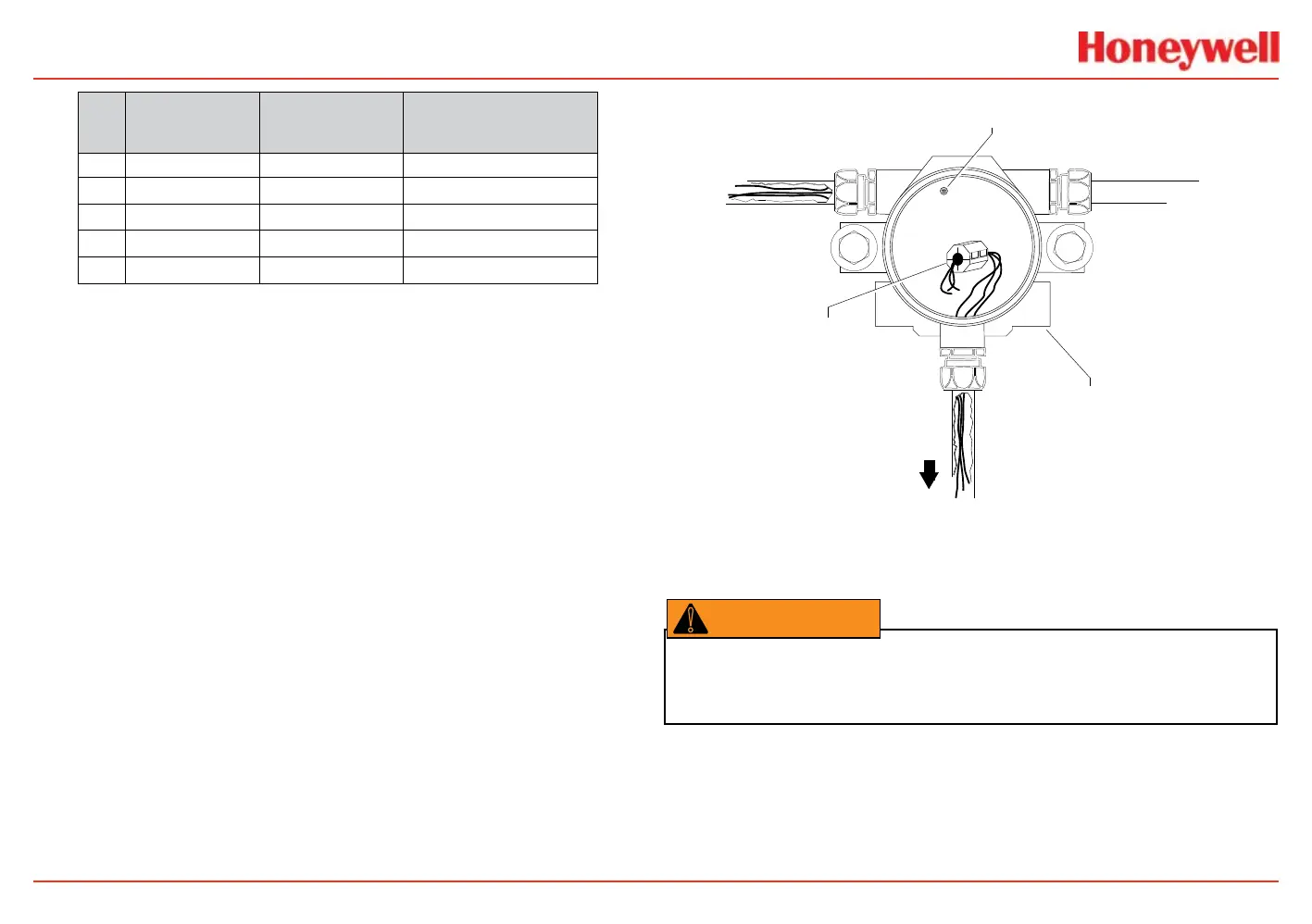
5. Wire the pluggable terminal block as shown in the mV
personality board illustration then plug the connector into
the back of the mV personality board. In remote mount
MPD congurations, the 3 wires connecting the pluggable
terminal block and the remote MPD must be routed
through the supplied ferrite bead (Honeywell Analytics
part no. 0060-1051, supplied in the accessory kit) as
shown in Figure 46.
Internal Ground Lug
(do not use)
Power
Ferrite Bead
for Remote
Sensor Wiring
mV
Remote
Sensor
XNX Universal Transmitter
Figure 46. Ferrite bead wiring
6. Mount the remote sensor junction box with sufcient room
below to t the sensor and weatherproof cover.
Warning: Install the junction box according to local codes and manufacturer’s
requirements.
7. Attach the conduit to the remote terminal box. The
junction box provides a mounting base for the sensor and
contains the associated electronic circuit.
8. In the remote junction box, connect the wires from the
transmitter to the 3-way terminal block in the terminal box.
 Loading...


