XNX Universal Transmitter
Installation and Operation
42
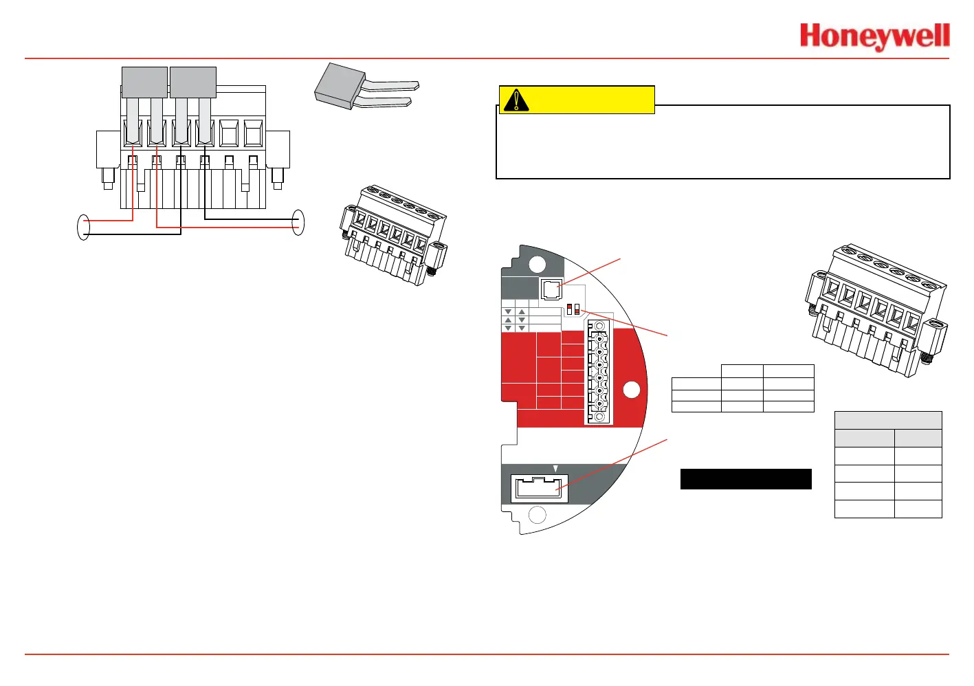
TB-1 Terminal Block
Terminal Block Jumper
IN
OUT
XNX EC TB-1
Figure 38. Pluggable terminal block and terminal block jumper
EC Personality Wiring
Caution: Do not force the POD into the enclosure. Doing so may result in damage to
the wiring or the POD or may alter the switch settings. If resistance is felt, wires may
be preventing the POD from being properly positioned.
!
TB1
Position EC
1 +24
2
3 0v
4
J1 - Local HART Connector
S1 and S2 - Signal Output
Jumper Switch
▼▼
▲
S2S1
Isolated
▼
Sink
▼
▲
Source
XNX EC TB-1
J2 - EC Barrier Connector
HART
20 mA
Operation
LOCAL
J1
S1
S1
Source
Sink
Isolated
S2
S2
EC Barrier
J2
+V 1-1
EC TB-1
4-20mA
HART
16-32 VDC
6.2W max.
1-2
-V 1-3
1-4
+mA 1-5
-mA 1-6
1
2
3
4
5
6
Figure 39. XNX EC personality board terminal blocks and jumper switches and terminal
block assignments
 Loading...


