XNX Universal Transmitter
Introduction
21
Controls and Navigation
Command Description
✓
Enter/Accept
The Enter/Accept switch is used to access menus,
accept changes and to answer “yes” to system
prompts.
✖
Escape/Back
The Escape/Back switch is used to return to previous
menus or to answer “no” to system prompts.
Move Left/
Decrease Value
The Left/Decrement arrow is used to move through
menu options or decrease values when entering text or
numbers.
Move Right/
Increase Value
The Right/Increment arrow is used to move through
menu options or increase values when entering text or
numbers.
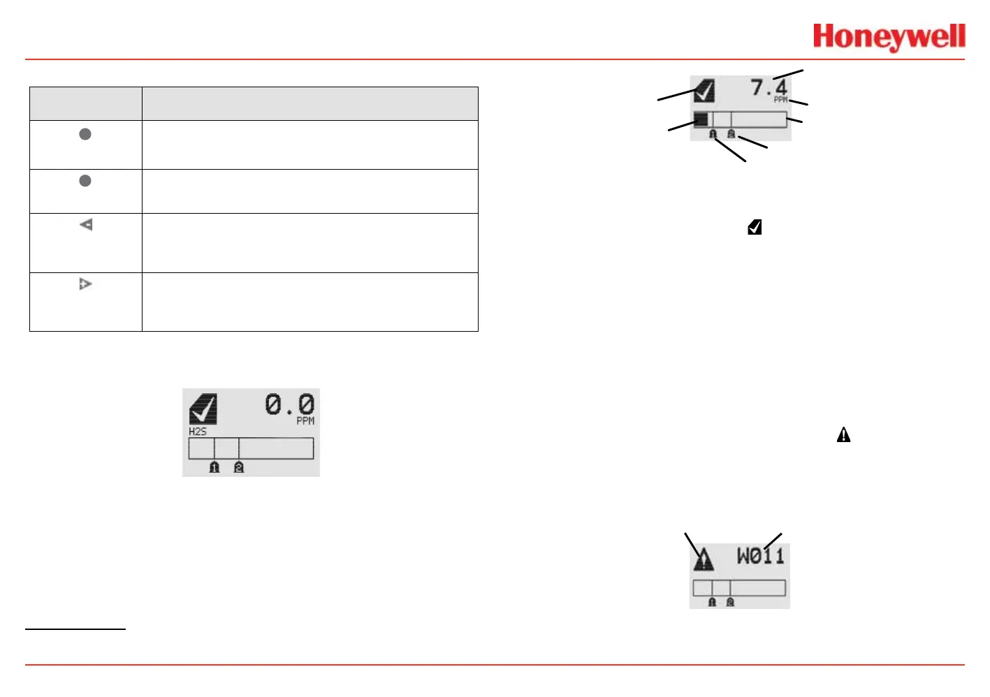
The General Status Screen
\
Figure 9. General Status screen
3
The General Status screen shows the status of the transmitter.
Warnings, faults, alarm levels, and current concentration levels
are displayed continuously.
3
The LCD screen’s refresh rates are 500 milliseconds when the LCD heater is off and 1 second
with the heater on.
Status Indicator
Current Concentration Level
(Numeric)
Alarm 2 Set Point
Alarm 1 Set Point
Current Concentration Le
vel
(Bar Graph)
Full Scale
Concentration Units
Figure 10. General Status screen, normal operating mode
The Normal Operating Mode icon indicates proper operation.
The display also shows the concentration level of the target gas
in two ways. In the rst, a numeric value is shown in the upper
right corner of the display in the units selected (ppm, %LEL,
%VOL). The second concentration display is shown in the form
of a bar graph representing the current concentration against
full scale and in relation to the dened alarm levels. For more
information on setting range and alarm levels, see the Range/
Alarm Settings section. See the EC Sensor Performance Data,
Factory Mutual Veried, EC Performance Data, DEKRA EXAM
Veried and the Other EC Sensors sections for negative drift and
zero deviation values.
When a warning is triggered, the warning icon
appears and
information is displayed on the General Status Screen. The
information displayed alternates between screens displaying the
gas concentration and the warning code. See the Warnings and
Faults section for more warning code information.
Figure 11. General Status Warning detail
 Loading...


