XNX Universal Transmitter
Specications
163
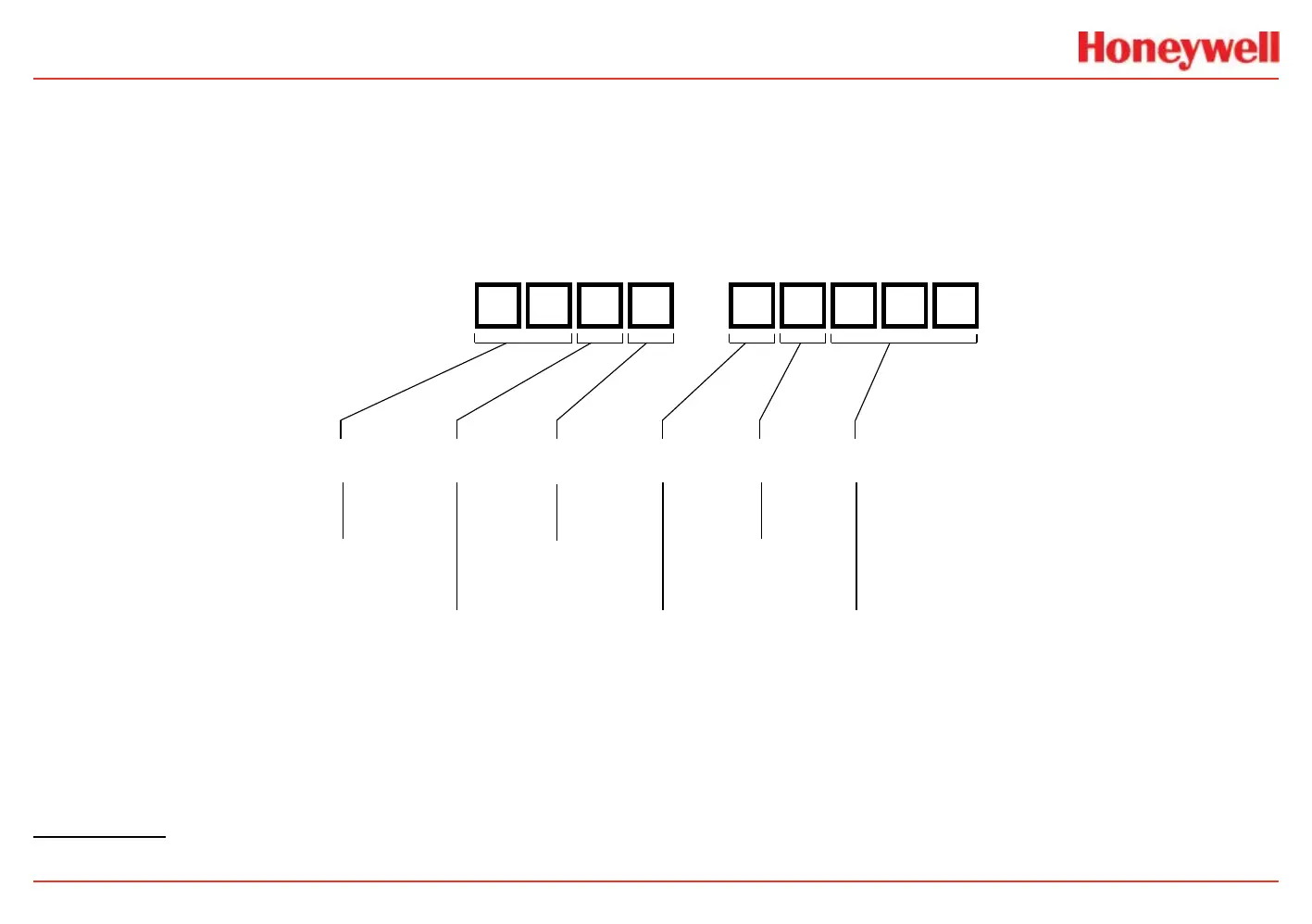
Product Identification
The part numbering system encodes all possible XNX configurations. The first four digits describe the enclosure and the sensor. The last
five describe the options (the three-digit sensor and range field is reserved for millivolt units). Agency approvals of MPD sensors vary
depending on sensor type and part number. Verify that the approvals of both the transmitter and the MPD sensor meet the requirements of
the installation.
XNX - -
Agency approval
and thread type
Enclosure
material
Sensor
personality
Interface
options
Local
HART
Sensor
and range
AM = ATEX/IEC M25
UT = UL/CSA 3/4” NPT
BT = INMETRO 3/4” NPT
or M25
A = Aluminum
S = Painted Stainless Steel
E = Electromechanical
I = Infrared
V = Millivolt
N = None
R = Relay
M = Modbus
F = Foundation Fieldbus
N = None
H = Local HART
NNN = None
CB1 = MPD-AM (Catalytic Bead %LEL)
IF1 = MPD-AMIF1 (IR %LEL Flammable)
IV1 = MPD-AMIV1 (IR CH 0-5% Vol)
IC1 = MPD-AMIC1 (IR CO 0-5% Vol)
2
4
1
1
1
1
1 Indicates agency approval and port thread specication
 Loading...


