XNX Universal Transmitter
Installation and Operation
38
6 Transmitters - Distance “d”
Configuration
18 AWG
[1.0 mm2]
16 AWG
[1.5 mm2]
14 AWG
[2.0 mm2]
12 AWG
[3.5 mm2]
XNX mV or EC
With Sensor
95 feet
[33 meters]
150 feet
[45 meters]
240 feet
[73 meters]
385 feet
[117 meters]
XNX IR with
Searchpoint Optima Plus
55 feet
[17 meters]
85 feet
[26 meters]
140 feet
[42 meters]
225 feet
[68 meters]
XNX IR with
Searchline Excel
45 feet
[14 meters]
70 feet
[21 meters]
115 feet
[35 meters]
185 feet
[56 meters]
Ensure that wiring is adequately protected from mechanical
damage during installation. Shorted or open-circuit wiring to an
MPD **I** sensor may result in a full-scale concentration reading
before the transmitter’s internal diagnostics can identify the
external installation fault.
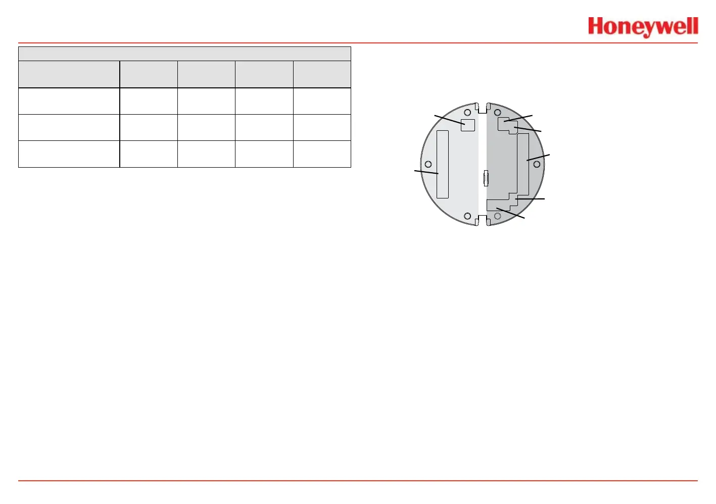
POD Connections
This illustration shows the connections available on of the
terminal blocks for each type of personality board.
J1 - Remote HART Connector Only
Personality
Boards
Option
Boards
A
B
C
D
E
F
Figure 33. Personality board terminal block legend
Each of the personalities uses a single terminal block for
connection with the exception of the IR personality, which
features a second terminal block.
The personality boards also provide a dedicated pair of jumper
switches to dene output of the transmitter as isolated 4-20mA,
Sink 20mA, or Source 20mA as well as a service jumper to allow
power to the loop to continue when the transmitter is being
serviced. A separate connector is used to activate local HART
(see the Local HART Interface section).
Local HART provides an external access to control the
transmitter. An intrinsically safe (IS) barrier inside the
transmitter allows the user to attach an external handheld eld
communicator for programming and conguration. The external
interface is intrinsically safe. It is installed in the transmitter’s
lower left cable/conduit port.
 Loading...


