XNX Universal Transmitter
Installation and Operation
51
XNX
+IR
Signal
-IR
R
L
1-7
1-9
1-8
+V
+mA
-V
mA Device
Current
Flow
24V 7W Max
XNX S3 and S4 must be in the UP position
Set mA Device and XNX to the same output type�
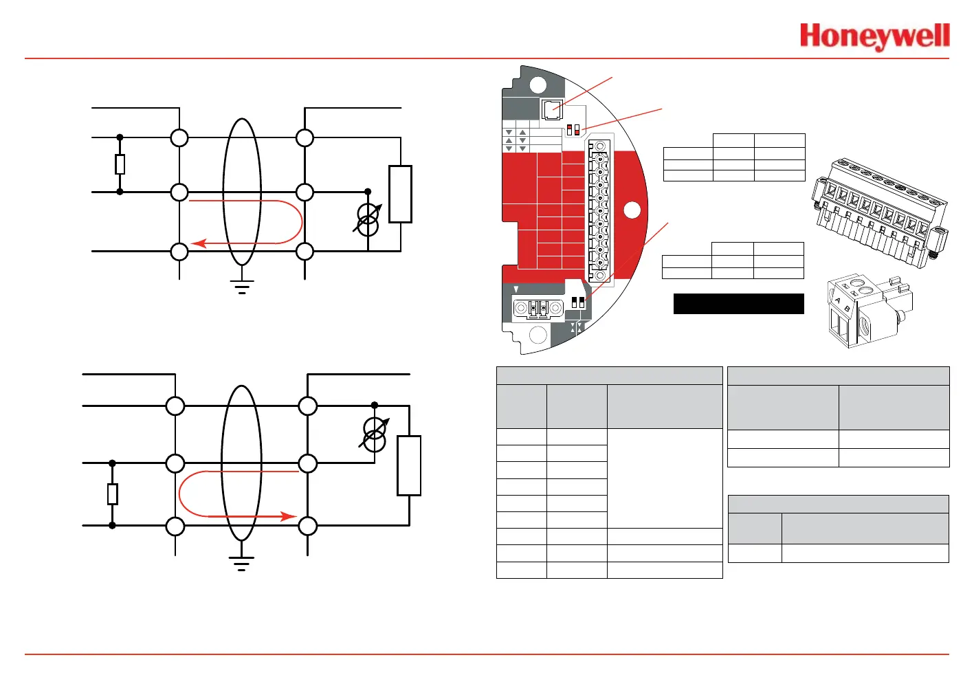
Figure 47. XNX mA input sink conguration
XNX
+IR
Signal
-IR
R
L
1-7
1-9
1-8
+V
-mA
-V
mA Device
Current
Flow
XNX S3 and S4 must be in the DOWN position
Set mA Device and XNX to the same output type�
Figure 48. XNX mA input source conguration
Note:
Honeywell Aanalytics recommends that Excel or Optima and the transmitter be wired to building ground.
Ground the system at only one point.
HART
20 mA
Operation
LOCAL
J1
S1
+V 1-1
Searchline
Searchpoint
4-20mA
HART
18-32 VDC
13.2W max.
1-2
-V 1-3
1-4
+mA 1-5
-mA 1-6
1-7
- Ir
+ Ir
1-8
Sig 1-9
S1
Source
Sink
Isolated
S2
S2
Ir TB-1
TB-2 Ir Data
S3
Source
Sink
S4
▼▼
▲▼
▼▲
S2S1
Isolated
Sink
Source
J1 - Local HART Connector
S1 and S2 - 20mA Output
Jumper Switch
S3 and S4 - IR 20mA Input
Jumper Switch
XNX IR TB-1
▼
▲
▼
▲
S4S3
Sink
Source
TB2
Terminal No.
From Searchpoint
Optima Plus
Searchline Excel
A Blue
B Orange
TB1
Terminal
No.
Desc.
From Searchpoint
Optima Plus
Searchline Excel
1 +24v
See the 4-20 mA
Output, Common
Connections, and Power
Settings section .
2
3 0 VDC
4
5 +20mA
6 -20mA
7 +24VDC Red
8 0VDC Black
9 Sig - 20mA White
XNX
Desc.
From Searchpoint Optima Plus
Searchline Excel
Earth Green/Yellow
1
2
3
4
5
6
7
8
9
TB1
TB2
Figure 49. IR personality
board terminal blocks,
jumper switches and wiring
guide
 Loading...


