172
• When Switch A works normally, Host accesses Switch A for portal authentication before accessing
the Internet; when Switch A fails, Host accesses the Internet through Switch B. The VRRP
uplink/downlink detection mechanism is used to ensure non-stop traffic forwarding.
• Use the RADIUS server as the authentication/accounting server. In this example, Server takes the
responsibilities of the portal server and the RADIUS server.
• Switch A and Switch B use the failover link to transmit stateful failover related packets and specify
VLAN 8 on the switches as the VLAN dedicated for stateful failover related packets.
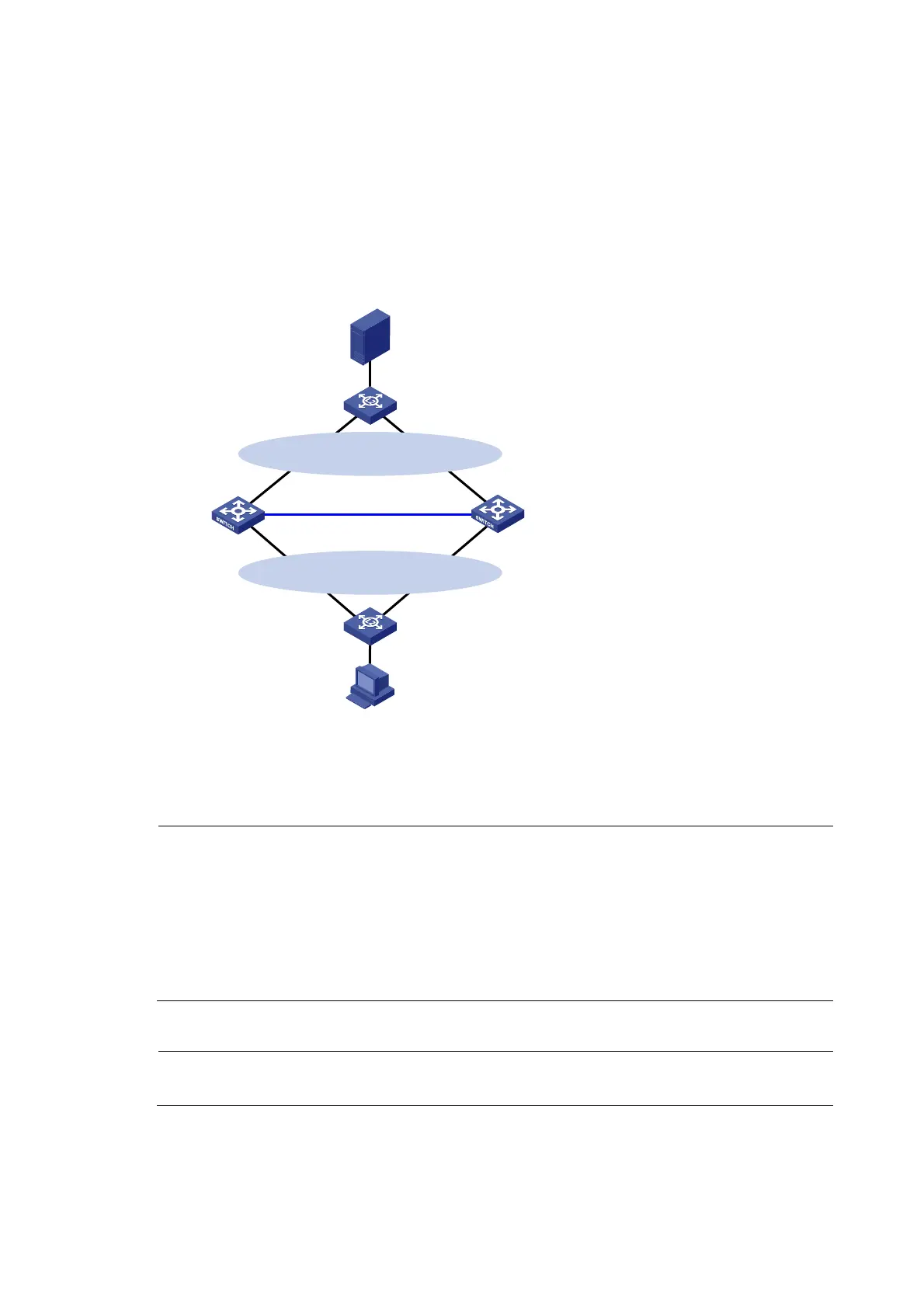
Figure 72 Network diagram
Switch A
Failover link
Host
IP: 9.9.1.2/24
Gateway: 9.9.1.1/24
Switch B
Vlan-int10
9.9.1.5/24
Vlan-int10
9.9.1.6/24
Vlan-int20
192.168.0.6/24
Vlan-int20
192.168.0.5/24
VLAN8
Virtual IP address 2:
192.168.0.1/24
Server
IP: 192.168.0.111/24
Gateway: 192.168.0.1/24
Master Backup
Virtual IP address 1:
9.9.1.1/24
Master
Backup
L2 Switch
L2 Switch
VLAN8
Configuration procedure
NOTE:
• Configure IP addresses for the host, server, and switches as shown in Figure 72 and m
ake sure that the
can reach to each other.
• Make sure that Host can access the authentication server through Switch A and Switch B respectively.
• Configure VRRP group 1 and VRRP group 2 to implement backup for downstream and upstream links
respectively. For more information about VRRP, see
High Availability Configuration Guide
.
• For information about stateful failover configuration, see
High Availability Configuration Guide
.
1. Configure the portal server (iMC PLAT 5.0)
NOTE:
This example assumes that the portal server runs iMC PLAT 5.0(E0101) and iMC UAM 5.0(E0101).
# Configure the portal server.
 Loading...