Guidelines for Marking
Powermax45 XP Operator Manual 809240 11 9
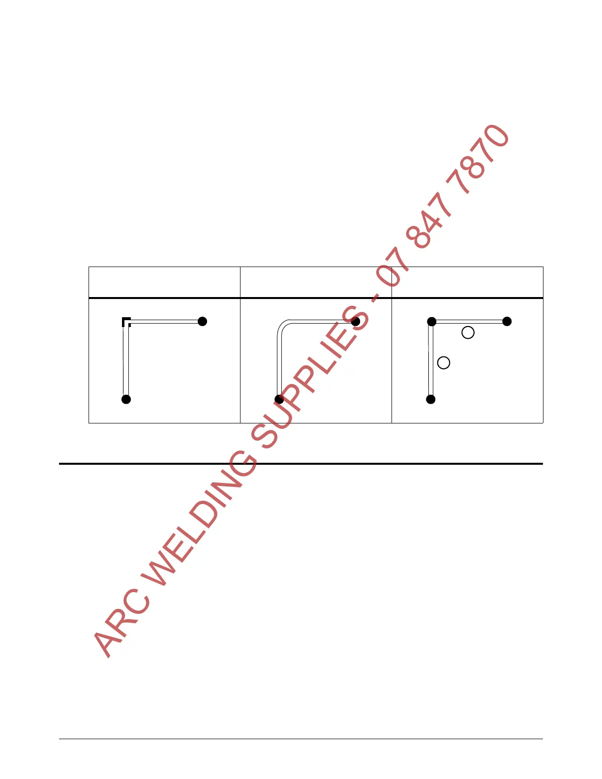
Cornering guidelines
Reduce both output current and marking speed for the entire marking operation.
Depending on the capabilities of your cutting table and CNC, you may need to try different
cornering methods to achieve the best possible results on 90° corners.
On many tables, it can be difficult to achieve a clean 90° corner. It requires the torch to
come to a complete stop for some length of time, which can result in a corner that is
wider and deeper than desired.
The rounded corner method shown below is recommended for most table/CNC
configurations. This method does not require the torch to come to a complete stop in
the corner.
If a sharper 90° corner is necessary, you can try the 2-step operation shown below.
However, this method does leave dimples at the “start” and “stop” points.
Marking troubleshooting tips
Factors that affect marking width, depth, and quality include:
Process gas – see the comparison of argon to air on page 114
Material type (mild steel, stainless steel, or aluminum)
Material thickness and surface finish
Plasma power supply output current (amperage)
Torch marking/dimpling speed
Torch standoff
Characteristics of the cutting table and CNC, such as how they handle delays,
accelerations, and decelerations
Gas pressure, if you manually adjusted the pressure to be outside the recommended range
automatically set by the system – see page 54
To optimize your marking or dimpling process and results, use the troubleshooting tips on page 120
and the cut charts starting on page 132.
90° corner – difficult to achieve
on many tables
Recommended method for
most tables/CNCs
Alternate 2-step operation
ARC WELDING SUPPLIES - 07 847 7870

 Loading...