Checkpoint
code display
v Remind button: This button places the system-error LED on the front panel into
Remind mode. In Remind mode, the system-error LED flashes rapidly until the
problem is corrected, the server is restarted, or a new problem occurs.
By placing the system-error LED indicator in Remind mode, you acknowledge
that you are aware of the last failure but will not take immediate action to correct
the problem. The remind function is controlled by the IMM.
v NMI button: Press this button to force a nonmaskable interrupt to the
microprocessor, if you are directed by IBM service and support.
v Reset button: Press this button to reset the server and run the power-on
self-test (POST). You might have to use a pen or the end of a straightened paper
clip to press the button. The reset button is in the lower-right corner of the light
path diagnostics panel.
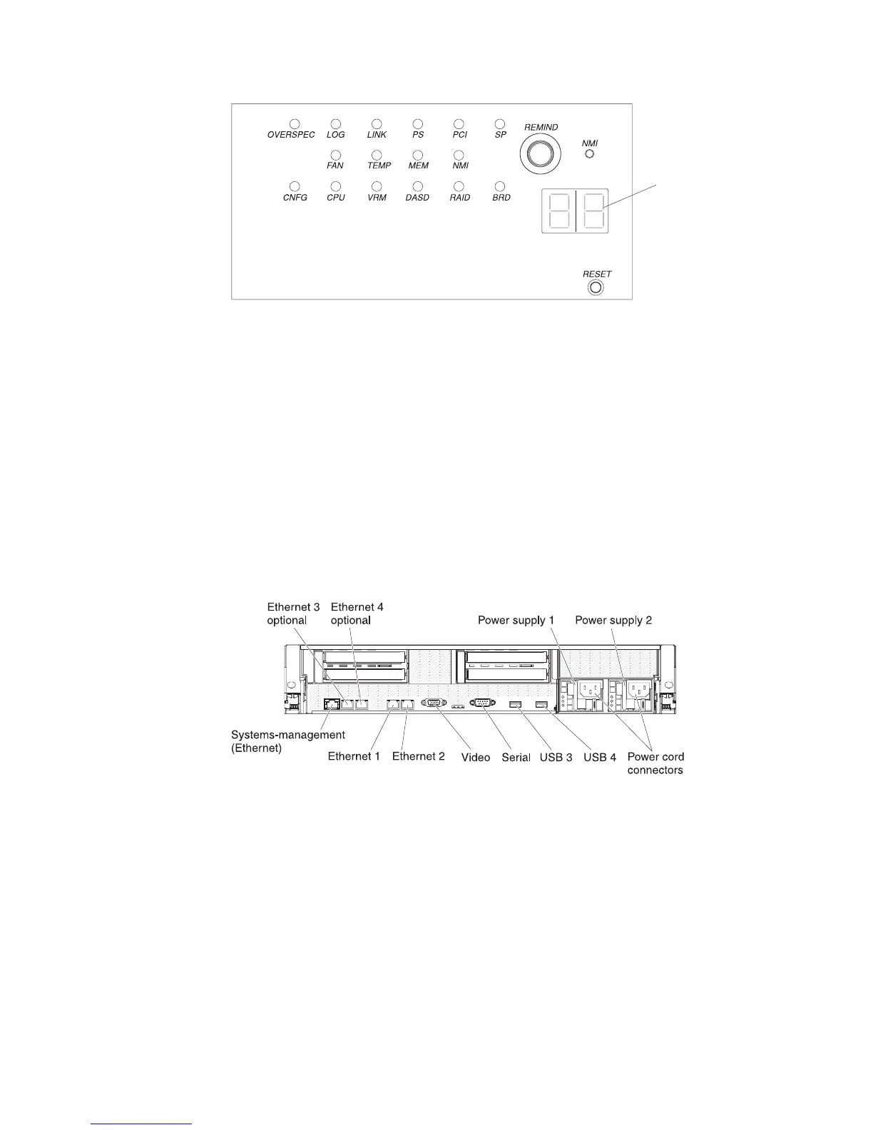
Rear view
The following illustration shows the connectors on the rear of the server.
Ethernet connectors: Use any of these connectors to connect the server to a
network.
Power-cord connector: Connect the power cord to this connector.
USB connectors: Connect a USB device, such as USB mouse, keyboard, or other
USB device, to any of these connectors.
Serial connector: Connect a 9-pin serial device to this connector. The serial port is
shared with the integrated management module (IMM). The IMM can take control of
the shared serial port to perform text console redirection and to redirect serial
traffic, using Serial over LAN (SOL).
Video connector: Connect a monitor to this connector. The video connectors on
the front and rear of the server can be used simultaneously.
12 IBM System x3650 M3 Types 4255, 7945, and 7949: Problem Determination and Service Guide
 Loading...


