5
2
PANEL DESCRIPTION
2
2001 NEW
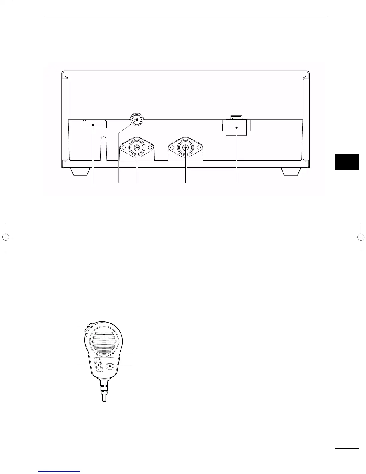
■ Rear panel— Main unit
q TUNER CONTROL SOCKET (pgs. 54, 56, 61)
Connects a control cable to an optional antenna
tuner.
A female connector kit is supplied for external an-
tenna tuner connection.
w
GROUND TERMINAL
IMPORTANT! Connects a ship’s (or vehicle’s)
ground. See pages 55 and 63–65 for details.
e ANTENNA CONNECTOR 1 (pgs. 54, 56)
Connects a 50 Ω HF band antenna via a 50 Ω
matched coaxial cable with a PL-259 plug for both
transmit and receive operation.
r ANTENNA CONNECTOR 2 (pgs. 54, 56)
Connects a 50 Ω HF band antenna via a 50 Ω
matched coaxial cable with a PL-259 plug for DSC
receiver.
t DC POWER SOCKET (p. 54, 61)
Accepts 13.6 V DC through the supplied DC power
cable.
■ Microphone (HM-135)
q PTT SWITCH [PTT]
Push and hold to transmit; release to receive.
w UP/DOWN SWITCHES [
∫∫
]/[
√√
]
Push either switch to change the operating channel,
frequency, etc.
e USER PROGRAMMABLE SWITCH [P]
Push to activate or deactivate a function, selected
in initial set mode (p. 51).
✔ For detailed “ANTENNA AND GROUNDING CON-
SIDERATIONS,” see pages 63 to 65.
IC-M802_USA.qxd 02.5.30 11:39 Page 5
 Loading...