True Scale Fabric Switches 12000 Series Hardware
July 2015 Installation Guide
Order Number: G91928004US 51
12000 Series Switches
2.9.1.2 User Site Installation
After final installation of a 12800-series switch is completed at the end user site:
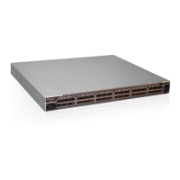
1. Disengage the thumb screw and partially rotate the lever as shown in Figure 48.
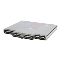
2. Peel off the protective label. Re-engage the lever and tighten the thumb screw as
shown in Figure 49.
2.9.2 Start-up Procedures
1. Power up the switch.
2. From its flash image on the management module, the switch begins its boot
process.
Note: If the DB9 port of the SEEB or the RS232 port on the 12200/12300 is connected to a
terminal emulation program, the user will be able to view the switch boot process. Be
certain to use a null-modem/crossover serial cable for the console port. For users
assembling their own cable, refer to Appendix C for serial port pinout information. The
settings for the terminal emulation device should be:
• 8 data bits
• no parity bits
• 1 stop bit
• 57.6K baud
• Use VT100 emulation.
Figure 48. MRL Protective Label 5
Figure 49. MRL Protective Label 6
 Loading...