GD200A series VFD Basic operation instruction
-104-
4. During the motor autotune 2, do not to de-couple the motor form the load if static autotune is
selected. Because only some parameters of the motor are involved, the control performance is not
as better as the rotation autotune. The asynchronous motors can autotune the parameters of P02.06
–P02.08. It is suitable in the cases which SVPWM control is applied.
7.6 Start and stop control
The start and stop control of the VFD includes three states: start after the running command during
normal powering on, start after the restarting function becomes valid during normal powering on and
start after the automatic fault reset. Below is the detailed instruction for three starting.
There are three starting modes for the VFD: start from the starting frequency directly, start after the
DC braking and start after the rotation speed tracking. The user can select according to different
situations to meet their needs.
For the load with big inertia, especially in the cases where the reverse rotation may occur, it is better
to select starting after DC braking and then starting after rotation speed tracking.
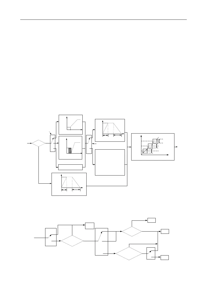
1. The starting logic figure of starting after the running command during the normal powering on:
Jogging running?
N
1f
1t
P00.11
ACC time
P00.12
DEC time
ACC
DEC
P00.03
Reserved
1f
1t
P08.07
ACC time
P08.08
DEC time
ACC
DEC
P08.06
1f
1t
Jumping
frequency 2
1/2*jumping range 2
1/2*jumping range 2
Jumping
frequency1
1/2*jumping range 1
1/2*jumping range 1
Jumping
frequency3
1/2*jumping range 3
1/2*jumping range 3
Y
Start after rotation speed tracking
P01.00
Starting running
Start directly
The starting frequency
The starting frequency
The retention time
The braking time before starting
The braking current before starting
P01.05
ACC/DEC method selection
0
1
2
0
1
Linear ACC/DEC
Start directly
Start after DC braking
Jogging frequency
2. The starting logic figure of starting after the restarting function becomes valid during the normal
powering on:
Stand
by
Running state
before power off
0
1
P01.21
Waiting time>P01.22
0
1
2
Stop
Run
0
1
P01.18
N
Y
Restart
after
power off
Run
Stop
FWD/REV
Operation command is
valid or not
N
Run
Y
P00.01
Keypad
Communication
Terminal
s
 Loading...

