GD200A series VFD Installation guidelines
-18-
Braking resistor
Output
reactor
Output
filter
018G/022P~030G/037P
For 1PH 220V: optional
3PH power
50/60Hz
Fuse
Input
reactor
Input
filter
R
S
T
U
V
W
PE
M
(+)
(-)
PB
A1
A2
Figure 4-7 Main circuit wiring diagram for the 018G/022P–030G/037P models
Input
reactor
Input
filter
Output
reactor
Output
filter
037G/045P
For 1PH 220V: optional
3PH power
50/60Hz
Braking unit
Braking
resistor
DC reactor
Fuse
R
S
T
U
V
W
PE
M
A1
A2
P1
(+)
(-)
DC-
DC+
Figure 4-8 Main circuit wiring diagram for the 037G/045P and higher models
Note:
The fuses, DC reactors, braking units, braking resistors, input reactors, input filters, output
reactors and output filters are optional parts. Please refer to Peripheral options and parts for
detailed information.
A1 and A2 are optional parts for the 018G/022P and higher models.
P1 and (+) are short circuited in factory, if need to connect with the DC rector, please remove
the contact tag between P1 and (+).
Before connecting the braking resistor cable, remove the yellow labels of PB, (+), and (-) from
the terminal blocks. Otherwise, poor connection may occur.
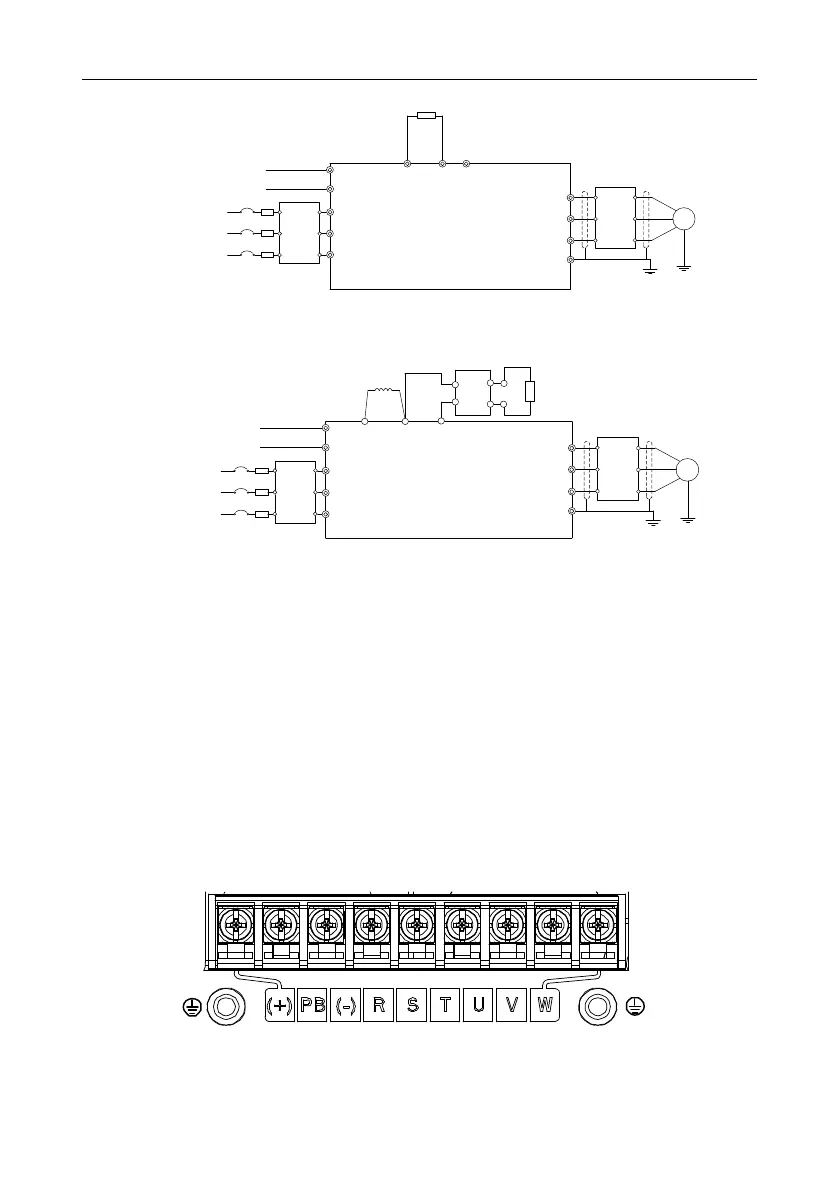
4.3.2 Terminals figure of main circuit
Figure 4-9 Main circuit terminals for the 0R7G–5R5G/7R5G models
 Loading...

