GD200A series VFD Peripheral options and parts
-160-
Appendix C Peripheral options and parts
C.1 What this chapter contains
This chapter describes how to select the options and parts of Goodrive200A series.
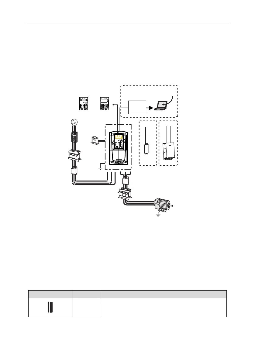
C.2 Peripheral wiring
Below is the peripheral wiring of Goodrive200A series VFDs.
Circuit
breaker
Input filter
Input reactor
Earth
DC reactor
LED
LCD
Standard
P1
+
+
-
PB
Braking
resistor
Braking
unit
PC
RS485
RS232
to
adapter
Output filter
Output reactor
Motor
Earth
+
Upper PC
software
485+
485-
Power supply
Optional
Note:
1. The 015G/018P and lower models have standard film keypad and the 018G/022P and higher
models have standard LED keypad.
2. The 030G/037P and lower models are embedded with braking unit.
3. Only the 037G/045P and higher models have P1 terminal and are connected with DC reactors.
4. The braking units apply standard braking unit DBU series in. Refer to the instruction of DBU for
detailed information.
Device to transfer the electronic signals
 Loading...

