EasyManuals Logo
Home>INVT>DC Drives>Goodrive200A Series

INVT Goodrive200A Series User Manual

INVT Goodrive200A Series
182 pages
To Next Page IconTo Next Page
To Previous Page IconTo Previous Page
Page #142 background imageLoading...
Page #142 background image
GD200A series VFD Communication protocol
-135-
Low bit of data 0004H
88H
High bit of data 0005H
00H
Low bit of data 0005H
32H
Low bit of CRC
C5H
High bit of CRC
6EH
END
T1-T2-T3-T4 (transmission time of 3.5 bytes)
The RTU response command is:
START
T1-T2-T3-T4 (transmission time of 3.5 bytes)
ADDR
02H
CMD
10H
High bit of write data
00H
Low bit of write data
04H
High bit of data number
00H
Low bit of data number
02H
Low bit of CRC
C5H
High bit of CRC
6EH
END
T1-T2-T3-T4 (transmission time of 3.5 bytes)
9.4.2 ASCII mode
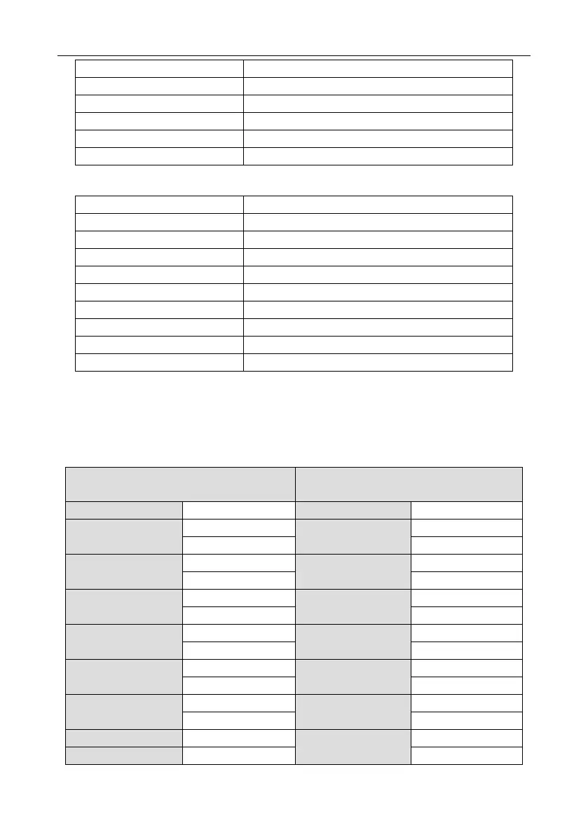
9.4.2.1 Command code: 03H (0000 0011), read N words (Word) (N16 words)
For instance: As for the VFD whose slave address is 01H, the starting address of internal storage is
0004, read two words continuously, the structure of this frame is listed as below:
ASCII master command message (the
command sent from master to the VFD
ASCII slave response message (the
message sent from VFD to the master)
START
‘: ’
START
‘: ’
ADDR
‘0’
ADDR
‘0’
‘1’
‘1’
CMD
‘0’
CMD
‘0’
‘3’
‘3’
High bit of starting
address
‘0’
Byte number
‘0’
‘0’
‘4’
Low bit of starting
address
‘0’
High bit of data address
0004H
‘1’
‘4’
‘3’
High bit of data number
‘0’
Low bit of data address
0004H
‘8’
‘0’
‘8’
Low bit of data number
‘0’
High bit of data address
0005H
‘0’
‘2’
‘0’
LRC CHK Hi
‘F’
Low bit of data address
0005H
‘0’
LRC CHK Lo
‘6’
‘0’

Table of Contents

Questions and Answers:

Question and Answer IconNeed help?

Do you have a question about the INVT Goodrive200A Series and is the answer not in the manual?

INVT Goodrive200A Series Specifications

General IconGeneral
BrandINVT
ModelGoodrive200A Series
CategoryDC Drives
LanguageEnglish

Related product manuals