EasyManuals Logo
Home>INVT>DC Drives>Goodrive200A Series

INVT Goodrive200A Series User Manual

INVT Goodrive200A Series
182 pages
To Next Page IconTo Next Page
To Previous Page IconTo Previous Page
Page #30 background imageLoading...
Page #30 background image
GD200A series VFD Installation guidelines
-23-
4.3.4 Wiring diagram of control circuit
-
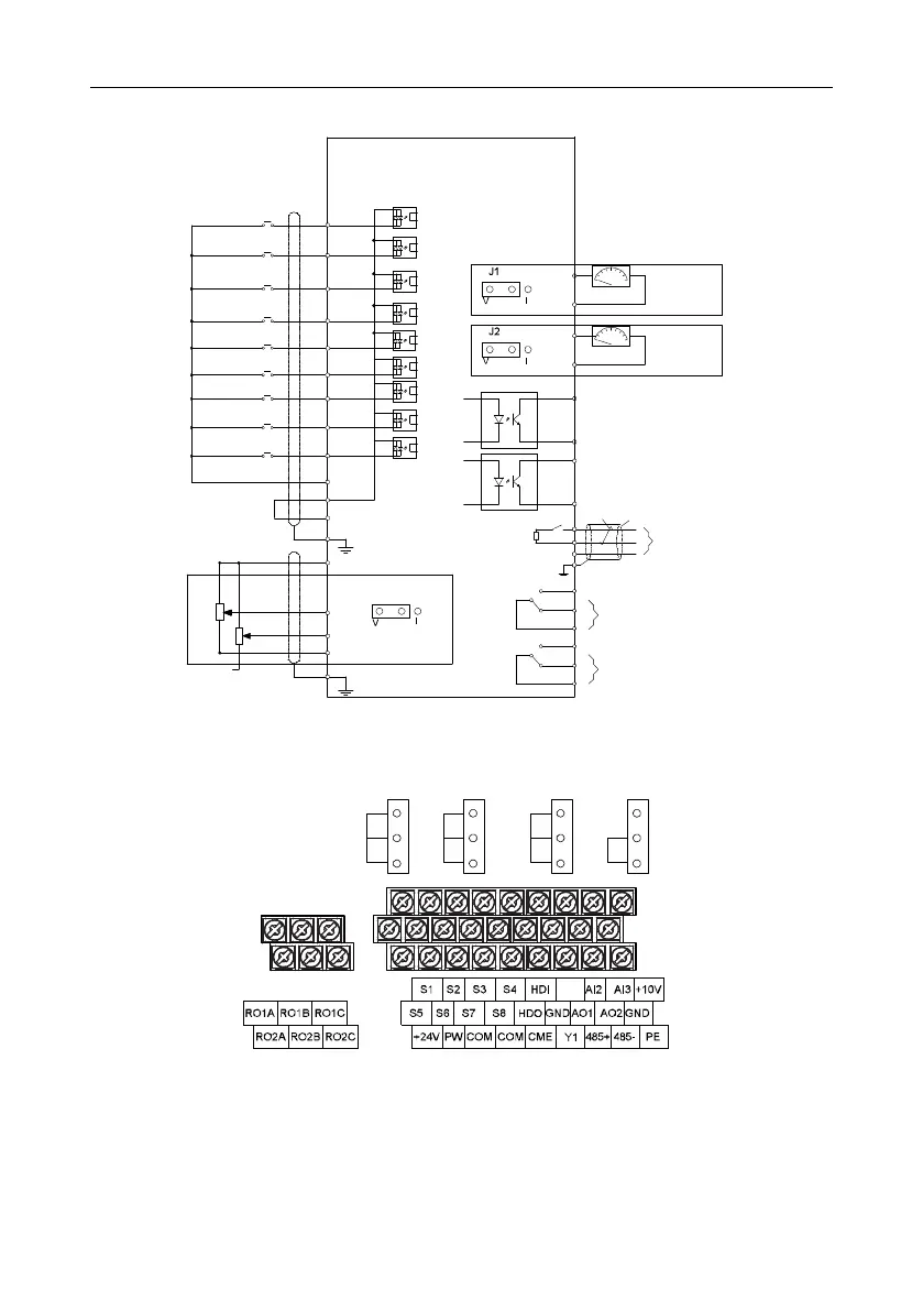
(externally connected)
10V
Shield
layer
Twisted
pair
Multifunction input terminal 1
Multifunction input terminal 2
Multifunction input terminal 3
Multifunction input terminal 4
Multifunction input terminal 5
Multifunction input terminal 6
Multifunction input terminal 7
Multifunction input terminal 8
High speed pulse input collector
Open collector input (optional)
+10 V power supply for frequency setting
+24V
PE
AI3 multi-function analog
input
AI2
J4
GND
PE
COM
PW
Relay 1 output
High-speed pulse output and open
collector output (optional)
Open collector output
RS485
communication
Analog output
0-10V/0-20mA
Analog output
0-10V/0-20mA
S1
S2
S3
S4
S5
S6
S7
S8
HDI
AO1
GND
GND
AO2
Y1
CME
CME
HDO
485+
485-
GND
J5
PE
RO1A
RO1B
RO1C
RO2A
RO2B
RO2C
Relay 2 output
Figure 4-19 Wiring diagram of the control circuit
4.3.5 Terminals of control circuit
V
AO1
AO2
A
I
2 485
I
V
I
V
I
ON
J4J1 J2 J5
Figure 4-20 Control circuit terminals for the 015G/018P and lower models

Table of Contents

Questions and Answers:

Question and Answer IconNeed help?

Do you have a question about the INVT Goodrive200A Series and is the answer not in the manual?

INVT Goodrive200A Series Specifications

General IconGeneral
BrandINVT
ModelGoodrive200A Series
CategoryDC Drives
LanguageEnglish

Related product manuals