GD200A series VFD Installation guidelines
-24-
Reserve
V
AO1 AO2
AI
2 485
I
V
I
V
I
V
I ON
J1 J2 J3 J4 J5
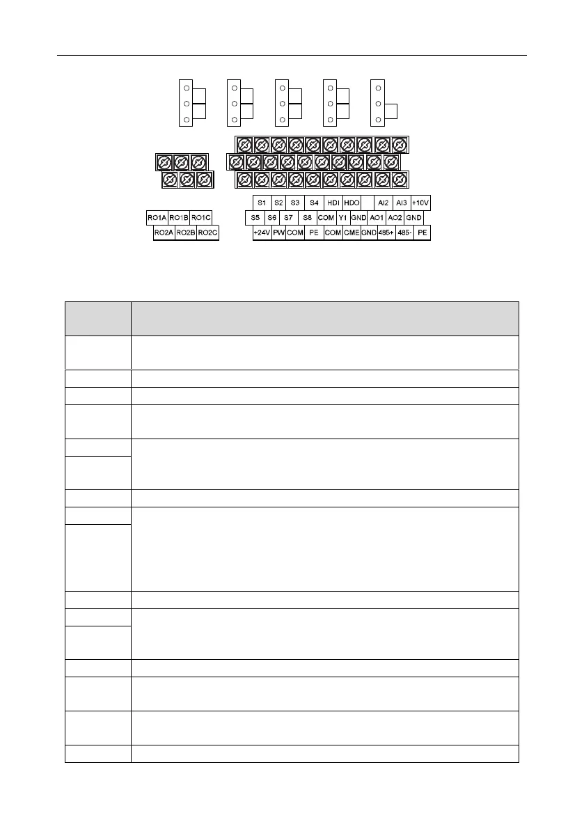
Figure 4-21 Control circuit terminals for the 018G/022P and higher models
Note: the spare terminal is reserved and not be used.
1. Switch output: 50mA/30V
2. Output frequency range: 0–50kHz
Common terminal of HDO and Y1, short-connected with COM in factory
1.Swtich capability: 50mA/30V
2.Output frequency range: 0–1kHz
485 communication interface and 485 differential signal interface
If it is the standard 485 communication interface, please use twisted pairs or
shield cable.
1. Input range: AI2 voltage and current can be chose: 0 (2)–10V/0 (4)–20mA;
AI2 can be shifted by J4; AI3: -10V–+10V
2. Input impedance: voltage input: 20kΩ; current input: 500Ω
3. Resolution: the minimum one is 5mV when 10V corresponds to 50Hz
4. Deviation ±1%, 25°C
+10V reference null potential
1. Output range: 0 (2)–10V or 0 (4)–20mA; AO1 can be shifted by J1; AO2 can be
shifted by J2
2. Deviation±1%,25°C
Provide the input switch working power supply from external to internal.
Voltage range: 12–30V
The VFD provides the power supply for users with a maximum output current of
200mA
 Loading...

