GD200A series VFD Dimension drawings
-154-
Appendix B Dimension drawings
B.1 What this chapter contains
Dimension drawings of the Goodrive200A are shown below. The dimensions are reference in
millimeters.
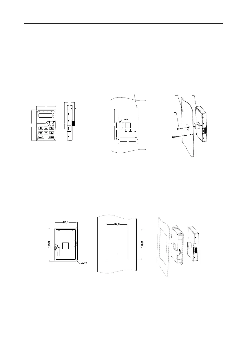
B.2 Keypad structure
B.2.1 Structure chart
Dotted frame is keypad outline
Keypad
Panel
2-M3×10 assembly screw
1934.4
19 20 .4
58
18
37 .1
8. 6
109.3
56
71 .3
6.7
109.3
71 .3
Hole dimension and diagram for keypad installation without bracket
B.2.2 Installation chart
Note: The external keypad can be fixed by M3 screws directly or the installation bracket. The
installation bracket for the 0R7G–030G/037P models is optional and the installation bracket for the
037G/045P–500G models is optional or substitutive by the external standard one.
Keypad bracket
Customer installation dimension
Figure B-1 Keypad Installation bracket (optional)
 Loading...

