GD200A series VFD Installation guidelines
-25-
1. Internal impedance: 3.3kΩ
2. 12–30V voltage input is available
3. The terminal is the dual-direction input terminal
supporting both NPN and PNP
4. Max input frequency: 1kHz
5. All are programmable digital input terminal. User can
set the terminal function through function codes.
Except for S1–S8, this terminal can be used as high frequency input channel.
max. input frequency: 50kHz
RO1 relay output, RO1A NO, RO1B NC, RO1C common terminal
Contactor capability: 3A/AC250V,1A/DC30V
RO2 relay output, RO2A NO, RO2B NC, RO2C common terminal
Contactor capability: 3A/AC250V,1A/DC30V
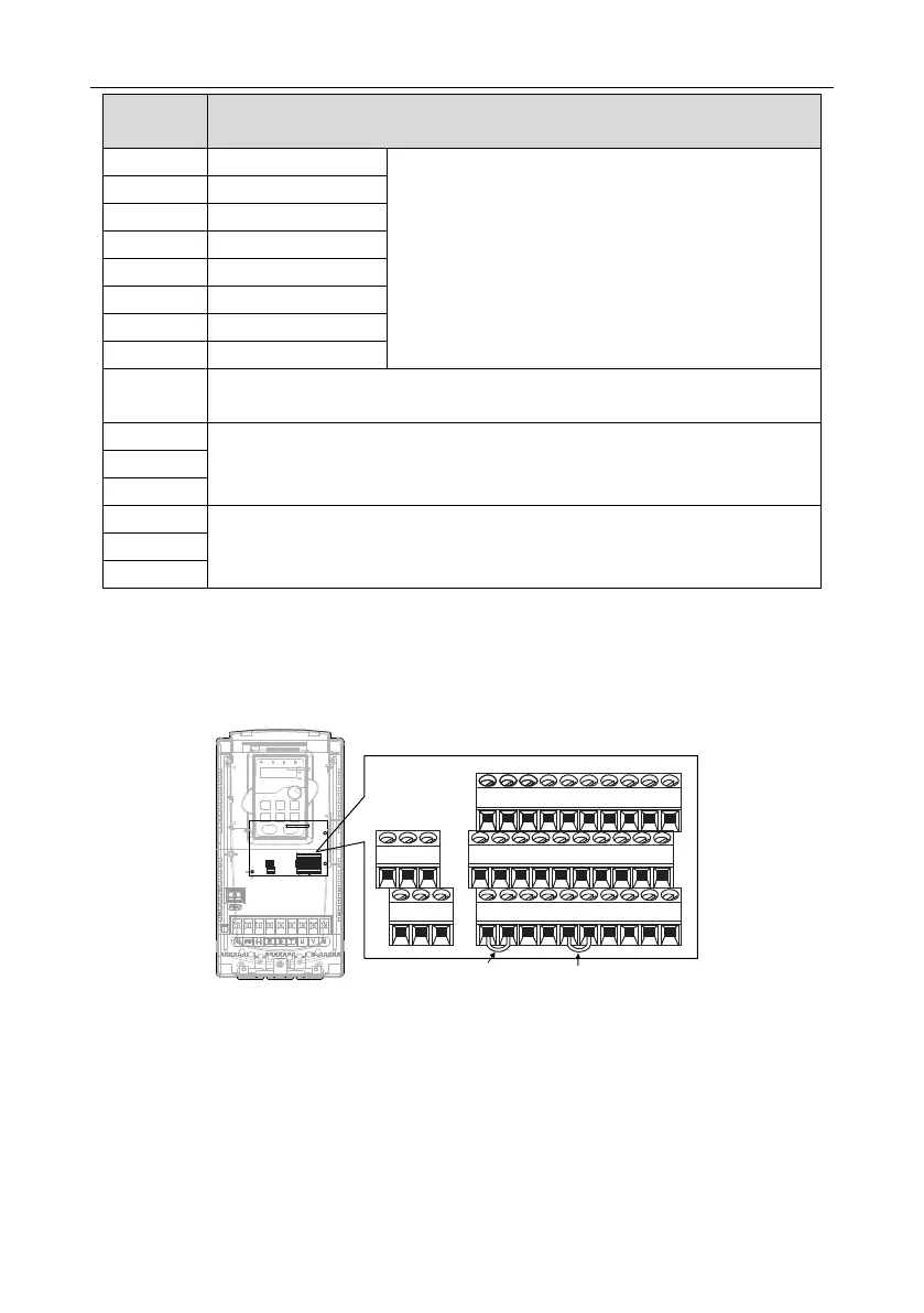
4.3.6 Input /Output signal connection figure
Please use U-shaped contact tag to set NPN mode or PNP mode and the internal or external power
supply. The default setting is NPN internal mode.
U-shaped contact tag
between
+24V and PW
U-shaped contact tag
between
COM and CME
Figure 4-22 U-shaped contact tag
If the signal is from NPN transistor, please set the U-shaped contact tag between +24V and PW as
below according to the used power supply.
 Loading...

