GD200A series VFD Installation guidelines
-21-
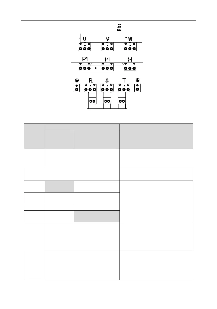
Figure 4-17 Main circuit terminals for the 355G/400P–500G models
For the
030G/037P and
lower models
For the 037G/045P and
higher models
Power input of the main circuit
3-phase AC input terminals which are
generally connected with the power
supply.
3-phase AC output terminals which are
generally connected with the motor.
This terminal is
inexistent
P1 and (+) are connected with the
terminals of DC reactor.
(+) and (-) are connected with the
terminals of braking unit.
PB and (+) are connected with the
terminals of braking resistor.
DC reactor terminal 2,
braking unit terminal 1
Braking resistor
terminal 2
This terminal is
inexistent.
380V: the grounding resistor is less than
10 ohms
Protective grounding terminals, every
machine is provided 2 PE terminals as the
standard configuration. These terminals
should be grounded with proper
techniques.
Optional for the 018G/022P and higher
models (connect to external 220V control
power). Power can be supplied via
auxiliary power, making it more
convenient for commissioning.
 Loading...

