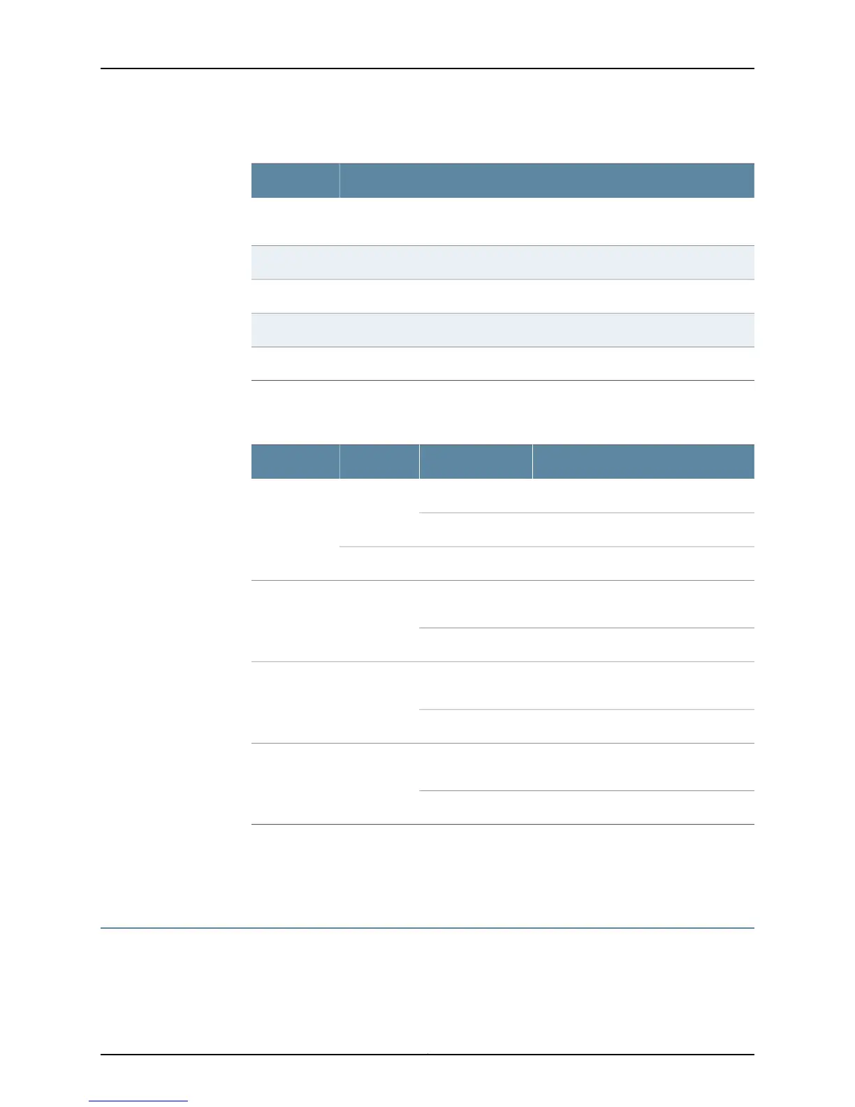
Table 5: AX411 Access Point Front Panel Features
ComponentNumber
Power connector (use only when not providing power to the access point with
PoE
1
Ethernet port for connecting the access point to the SRX Series device2
Console port for diagnostics and troubleshooting3
Slot for securing the access point with a standard laptop locking cable4
LEDs; described in Table 6 on page 105
Table 6 on page 10 describes the access point LEDs.
Table 6: AX411 Access Point LEDs
DescriptionStateColorName
The access point is receiving power.On steadilyGreenPower
The access point is off.Off
The access point is starting up.On steadilyRed
The access point is being managed by the
SRX Series Services Gateway.
On steadilyGreenStatus
The access point is unmanaged.Off
The 5 GHz radio is enabled and
broadcasting.
FlashingBlue5 GHz Radio
The 5 GHz radio is disabled.Off
The 2.4 GHz radio is enabled and
broadcasting.
FlashingGreen2.4 GHz Radio
The 2.4 GHz radio is disabled.Off
Related
Documentation
AX411 Access Point Rear Panel on page 10•
• AX411 Access Point Features on page 11
AX411 Access Point Rear Panel
Figure 5 on page 11 shows the rear panel of the AX411 Access Point.
Copyright © 2012, Juniper Networks, Inc.10
AX411 Access Point Hardware Guide
 Loading...