IEEE-488 PROGRAMMING
store, stop scan.
Format with loca-
tions, channels.
Loop for all 80
readings.
Get 199 reading.
Display reading.
Loop back for next
reading.
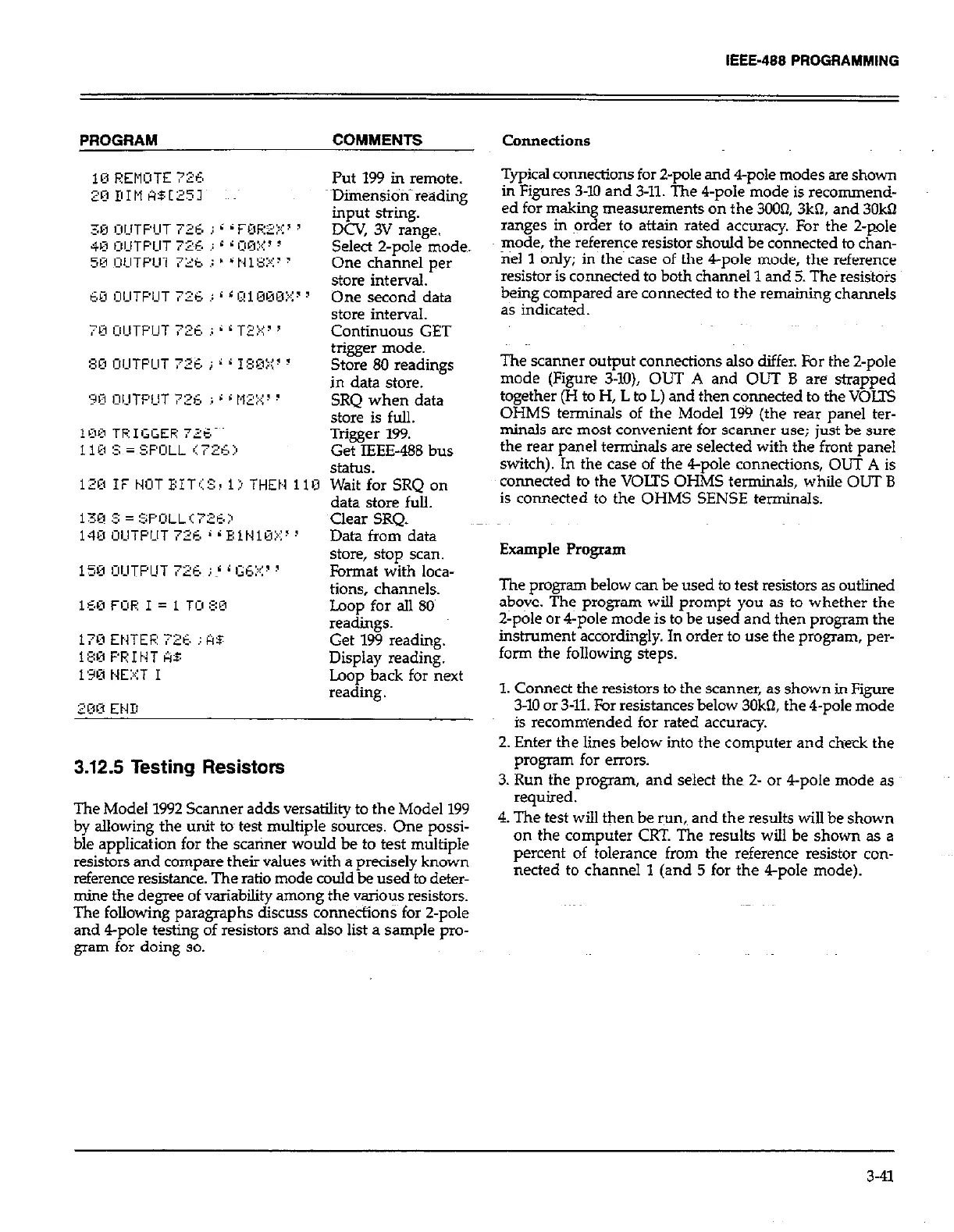
3.12.5 Testing Resistors
The Model 1992 Scanner adds versatility to the Model 199
by allowing the unit tom test multiple sources. One possi-
ble application for the scanner would be to test multiple
resistors and compare their values with a precisely known
reference resistance. The ratio mode could be used to deter-
mine the de-e of variability among the various resistors.
The following paragraphs discuss connections for 2-p&
and 4-pole testing of resistors and also list a sample pro-
gram for doing so,
Connections
Typical connections for 2-pole and 4-pole modes are shown
in Figures 3-10 and 3-U. The 4-pole mode is recommend-
ed for making measurements on the 3003,3kfl, and 3Okfl
ranges in order to attain rated accuracy. For the 2-pole
mode, the reference resistor should be connected to chan-
nel 1 only; in the case of the 4-pole mode, the reference
resistor is connected to both channel 1 and 5. The resiSto?s
being compared are connected to the remaining channels
as indicated.
The scanner output connections also differ. For the Z-pole
mode (Figure 3-lo), OUT A and OUT B are strapped
together (H to H, L to L) and then c~onnected to the VOLTS
OHMS terminals of the Model 199 (the rear panel ter-
minals are most convenient for scanner use; just be sure
the rear panel terminals are selected with the front panel
switch). In the case of the 4-pole connections, OUT A is
connected to the VOLTS OHMS terminals, while OUT B
is connected to the OHMS SENSE terminals.
Example Program
The program below can be used to test resistors as outlined
above. The program will prompt you as to whether the
2-pole or 4-pole mode is to be used and then program the
instrument accordingly. In order to use the program, per-
form the following steps.
1. Connect the resistors to the scanner, as shown in Figure
3-10 or 3-U. For resistances below 3Ok% the 4-pole mode
is recommended for rated accuracy.
2. Enter the lines below into the computer and check the
program for errors.
3. Run the program, and select then 2- or 4-pole mode as
required.
4. The test will then be run, and the results will be shown
on the computer CRT. The results will be shown as a
percent of tolerance from the reference resistor con-
nected to channel 1 (and 5 for the &pole mode).
3-41
 Loading...