BASIC DMM OPERATION
2.6.7 TRMS AC Voltage Measurements
Setiling Time-&c to within 0.1% of change in reading.
This time specification does not include A/D conversion
The in.Wument can make TFNS AC voltage mez+rements
from 1pV to 3OOV. To m&Wire AC volts, proceed as follows:
1. Select the AC volts function by pressing the VOLTS and
AC buttons.
2. Select a range consistent with the expected voltage or
use autorange.
3. Select the front or rear panel input terminals using the
INPUT switch.
NOTE
Caution :
There is a small amount of offset (typicaUy 150
Maximum input = 300V RMS. 425V Peak, 1 d V. Hz
counts at 5*/zd) present when using. the ACV
Input Impedance = 1 MR Shunted by < 1 OOpF
time.
AC Voltage
SOWX
MODEL 199
function. Do n&zero this level o&Paragraph
2.610 provides an explanation of AC voltage
offset.
Figure 2-6. TRMS AC Voltage Measurement
4. Con&a the signal to be measured to the selected in-
put terminals as shown in Figure 2-6.
2.6.8 Current Measurements (DC or TRMS AC)
5. Take the reading from the display.
The Model 199 can make DC or TRMS AC current
Clarifications of TRMS ACV Specificatioik
measurements from lOOn.4 (at Wtd resolution) to 3A. Use
the following procedure to make current measurements.
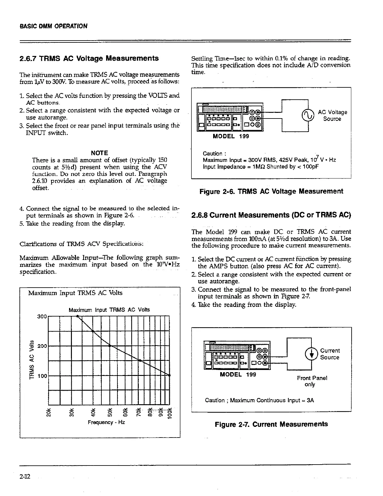
Maximum AIlowable Input-The following graph sum-
ma&es the maximum input based on the lOY*Hz
1. Select the DC current or AC -nt ‘Kiticfion by prrssing
specification.
the AMPS button (also press AC for AC current).
2. Select a range consistent with the expected current or
use autorange.
Maximum Input TRMS AC Volts
3. Connect the signal to be measured to the front-panel
input terminals as shown in Figure 2-7.
4. Take the reading from the display.
Maximum Input TRMS AC Volts
MODEL 199
Front Panel
Caution ; Maximum Continuous input = 3A
Figure 2-7. Current Measurements
2-12
 Loading...