AL Select the AC4 function and autorange. Do not use zero
to cancel any offset in this procedure.
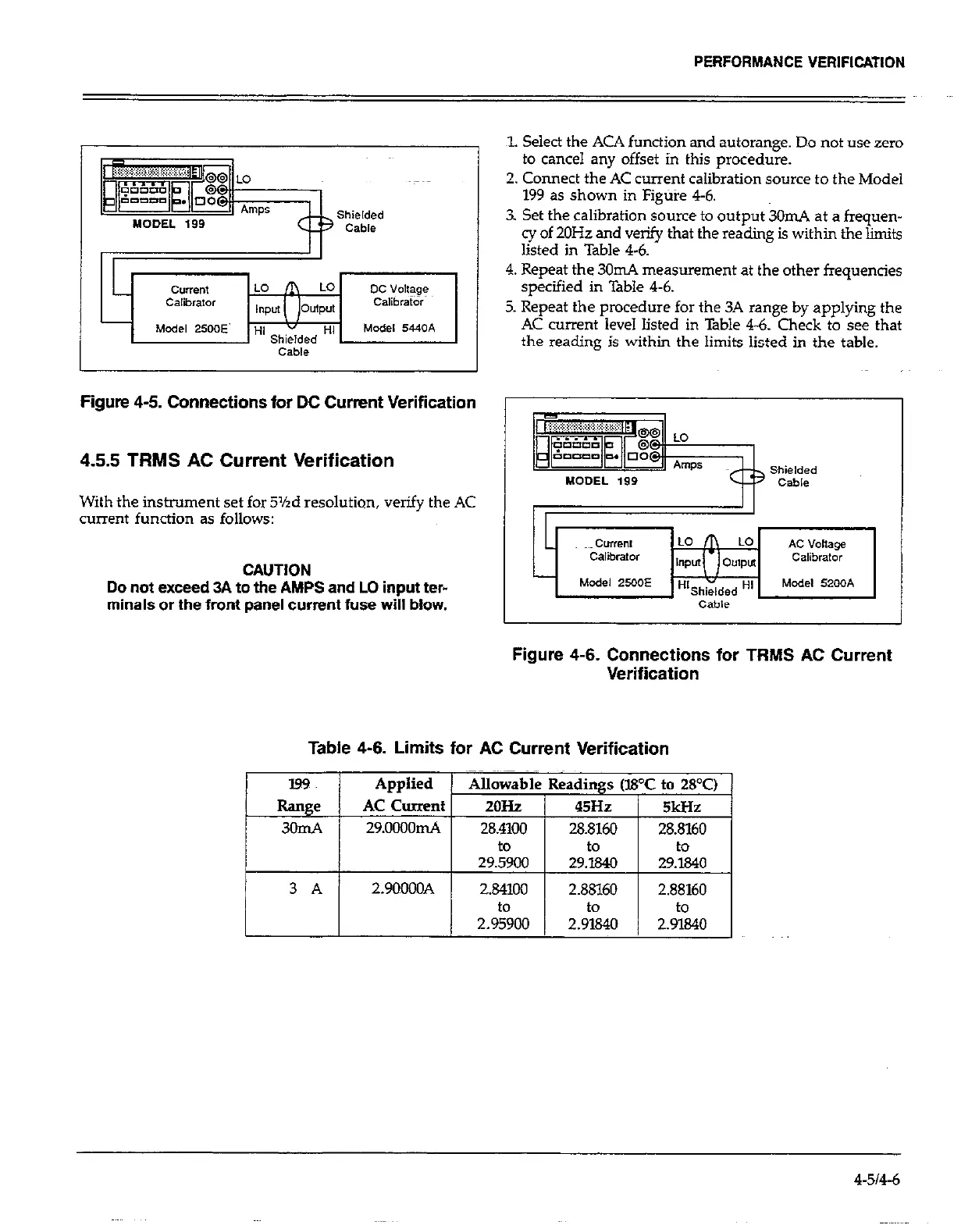
2. Connect the AC current calibration source to the Model
199 as shown in Figure 4-6.
3. Set the calibration source to output 3OmA at a frequen-
cy of 2OHz and verify that the reading is within the limits
listed in Table 4-6.
4. Repeat the 30111.4 measurement at the other frequencies
specified in Table 4-6.
5. Repeat the procedure for the 3A range by applying the
AC current level listed in Table 4-6. Check to see that
the reading is within the limits listed in the table.
Figure 4-5. Connections for DC Current Verification
4.55 TRMS AC Current Verification
With the instrument set for 5%d resolution, verify the AC
current functic
m as follows:
CAUTION
-~ pjyyijgjigj~~
Do not exceed 3A to the AMPS and LO inputter-
minals or the front panel current fuse will blow.
cam
Figure 4-6. Connections for TRMS AC Current
Verification
Table 4-6. Limits for AC Current Verification
I
3 A 2.9OOOOA 2.841Ou
2.88160 2.88160
to to
to
4-514-6
 Loading...