MAINTENANCE
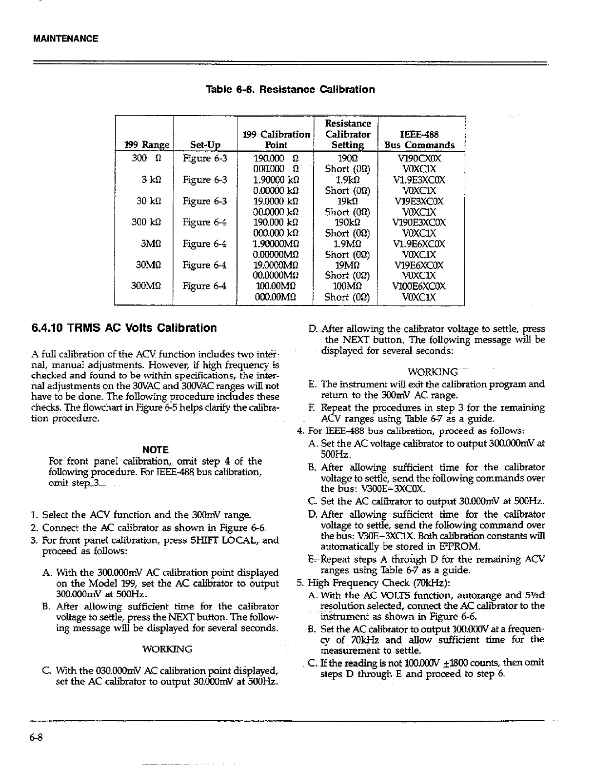
Table 6-6. Resistance Calibration
199 Range
300 0
3 kll
30 kQ
300 ko
3MQ
3OMil
3OOMQ
set-up
Figure 6-3
Figure 6-3
Figure 6-3
Figure 6-4
Figure 6-4
Figure 6-4
Figure 6-4
5
6.4.10 TRMS AC Volts Calibration
l99 Calibration
Point
lYo.m n
oomm a
1.90000 kQ
O.OCUW kQ
lY.OOQO kt-l
OO.OMX kt2
190.000 kf2
OOO.ooO kR
l.Yo#oMtl
OIJCPXIOMQ
lY.OOOOMR
001MooM62
l!N.OOMQ
OoO.oOMQ
A full calibration of the ACV function includes two inter-
nal, manual adjustments. However, if high frequency is
checked and found to be within specifications, the inter-
nal adjustments on the 3OVAC and 3OOVAC ranges will not
have to be done. The following procedure indudes these
checks. The flowchart in Figure 6-5 helps clarify the calibra-
tion procedure.
NOTE
For front panel caIibration, omit step 4 of the
following procedure. For IEEE- bus calibration,
omit step_%
Resistance
Calibrator
S&tillg
19ot-l
Short (On)
1.9kt-J
Short (00)
19kt-l
Short (On)
19OkQ
Short (On)
l.YMQ
Short (0’2)
19Mfl
Short (Ofi)
1OOMtl
Short (On)
IEEE-488
Bus Commands
vlYocxox
VCKClX
V1.9E3XCOX
VOXCIX
v19E3xccK
VOXClX
vlYoE3xcox
VOXClX
VL9E6XCOX
VOXClX
VlYE6XCOX
voxclx
VlOoE6xcOX
voxclx
D. After allowing the calibrator voltage to settle, press
the h%XT button. The following message will be
displayed for several seconds:
E. The instrument will exit the calibration program and
return to the 3OOmV AC range.
F. Repeat the procedures in step 3 for the remaining
ACV ranges using Table &7 as a guide.
4. For IEEE-488 bus calibration, proceed as follows:
A. Set the AC voltage calibrator to output 3OO.OOOmV at
5cQHz.
B. After allowing sufficient time for the calibrator
voltage to settle, send the following commands over
the bus: V3OOE-3XCOX.
1. Select the ACV function and the 3QOmV range.
”
7 Cnnn~rt thus AC nlihrdnr I)F ehnwn in Figure 66.
-. ___I.__. _..- .-- --.1.-.-. -I I.._ ..I. -
3. For front panel calibration, press Sm LQCAL, and
yL”ccF” Pa ,“Y”v”a.
C. Set the AC calibrator to output 3O.OOOmV at 5OOHz.
D. After allowina sufficient time for the calibrator
voltage to set&, send the following command over
the bus: WE-3XClX. Both calibration constants will
automatically be stored in EzPROM.
E~;~Reueat s&us A throtieh D for the remaininc ACV
A. With the 3CKKQOmV AC calibration point displayed
r&ges t&g Table 6-yas a guide.
on the Model 199, set the AC calibrator to output
5. High Frequency Check (7OkHz):
3C0.OOOmV at 5OOHz.
A. With the AC VOLTS function, autorange and 5%d
B. After allowing sufficierit time for the calibrator
resolution selected, connect the AC calibrator to the
voltage to settle, press the NEXT button. The follow-
~instrument as shown in Figure 6-6.
ing message will be displayed for several seconds.
B. Set the AC calibrator to output lOO.CX?OV at a frequen-
WORKING
cy of, 7Ok& and a&w sufficient time for the
measurement to settle.
C With the 030.OOOmV AC calibration point displayed,
set the AC ca&rator to output 3O.ooOmV at 5OOHz.
C. If the reading is not lKl.OKlV &I800 counts, then omit
steps D through E and proceed to step 6.
 Loading...