BASIC DMM OPERATION
press the NEXT key. The unit will then display the data
value at that location along with the measurement func-
tion in effect ate the time the data was taken.
5. To exit the recall mode, press NEXT while normal recall
data is displayed. RCL Will turn off ~to indicate that recall
has been disabled.
NOTES:
1. If data store has no valid data to display, the unit will
display the following message upon entry to the recall
mode.
NO DATA
2.~The unit will continue to store data while in recall until
the data store buffer is full (or continuously in wrap
around mode).
2.11 SCANNER OPERATION
(WITH OPTION 1992)
With the optional Model 1992 Scanner installed, the Model
199 &m scan four, 4-pole channels, or eight, 2-pole chan-
nels. The following paragraphs discuss scanner program-
ming, connections, atid operation from the front panel.
Refer to paragraph 3.12 for IEEE-488 scar&r programm-
ing. For scanner installation procedures, refer tom Section 6.
2.11.1 Scanner Connections
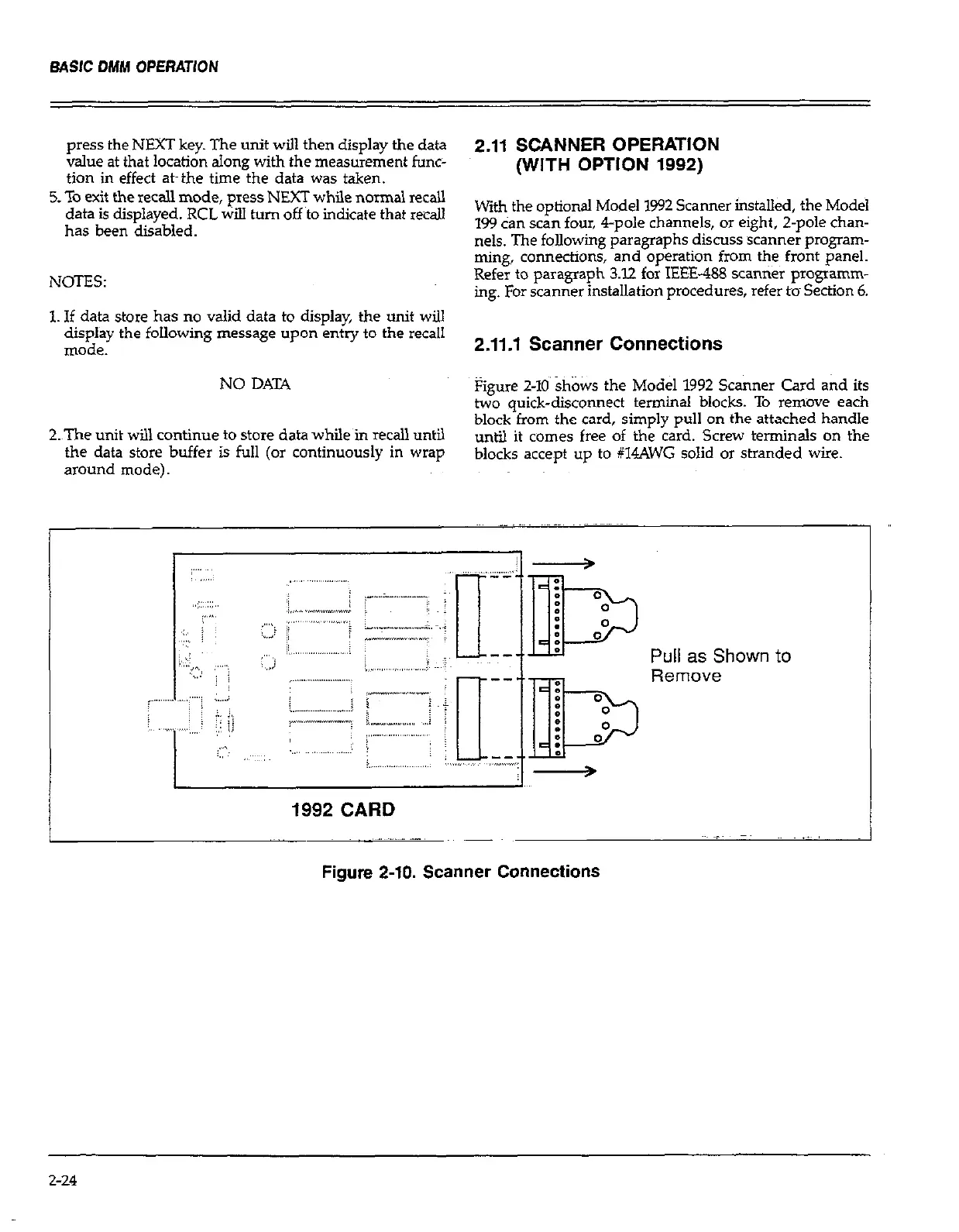
Figure 2-10 shows the Model 1992 Scanner Card and its
two quick-disconnect terminal blocks. To remove each
block from the card, simply pull on the attached handle
until it comes free of the card. Screw terminals on the
blocks accept up to #14AWG solid or stranded wire.
1992 CARD
Figure 2-10. Scanner Connections
2-24
 Loading...