&n~ 87 q 6 B5 84 83 B2 Bl BO
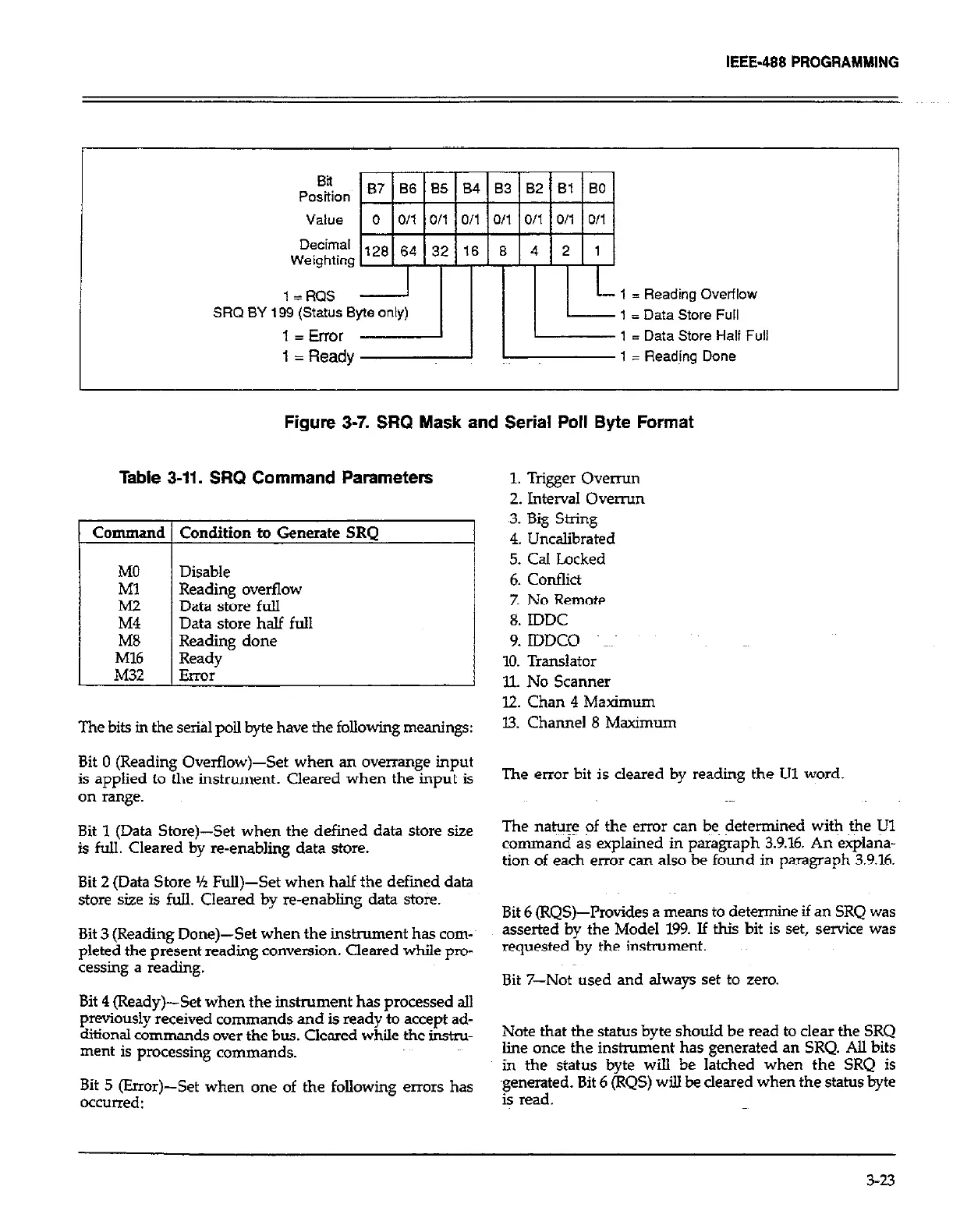
Figure 3-7. SRQ Mask and Serial Poll Byte Format
Table 3-11. SRQ Command Parameters
Command Condition to Generate SRQ
MO Disable
zi
Reading overflow
Data store full
M4 Data store half full
M8 Reading done
Ml6 Ready
M32 Error
The bits in the serial poll byte have the following meanings:
1. Trigger Ovemn
2. Interval overrun
,3. Big String
4. Uncalibrated
5. Cal Locked
6. Conflict
7. No Remote
8. IDDC
9. IDDCO magi
10. Translator
Il. No Scanner
12. Chan 4 Maximum
13. Channel 8 Maximum
Bit 0 (Reading Overflow)-Set when an overrange input
is applied to the instrument. Clexed when the input is
The error bit is cleared by reading the Ul word.
on range.
Bit 1 (Data Store)-Set when the defined data store size
The n&w: of the error can beg determined with the Ul
I kr .a-,,&L7 data s@re.
command as explained in paragraph 3.9.16. An explana-
tion of each error can also be found in paragraph 3.9.16.
Bit 2 (Data Store % Full)-Set when half the defied data
store size is full. Cleared by re-enabling data stoic.
Bit 6 (RQS)--Provides a means to Deb ‘* ^-^ tennUke d an bKv was
Bit 3 (Reading Done)-Set when the instrument has CO~-~
asserted by the Model 199. If this 1
bit is set, service was
pleted the present reading conversion. Cleared while pro-
requested b ”
y me uwrurnenr.
cessing a reading.
Bit 7-Not used and always set to zero.
Bit 4 (Ready)-Set when the instrument has processed all
previously received commands and is ready to accept ad-
ditional commands over the bus. Cleared while the in&u-
Note that the status byte should be read to clear the SRQ
ment is processing commands.
line once the instrument has generated an SRQ. All bits
in the status byte will be latched when the SRQ is
Bit 5 (Error)-Set when one of the following errors has
generated. Bit 6 (RQS) ~2 be deared when the status byte
occurred:
is read.
3-23
 Loading...