MAINTENANCE
21. Turn off the instrument power, and unplug the con-
netting blocks. Remove the shorting jumpers from the
to connect the relay shields to analog ground (see Figure
6-U). If desired, this jumper can be cut~to float the shields,
channel inputs. Assuming the scanner card functioned
normally, the unit is now reading for use.
or to connect another potential (for example, for guarding).
CAUTION
6.8.3 Relay Shield Jumper
Maximum voltage between shields and contact
is 250V DC.
A jumper (Wl), on the scanner board, is factory installed
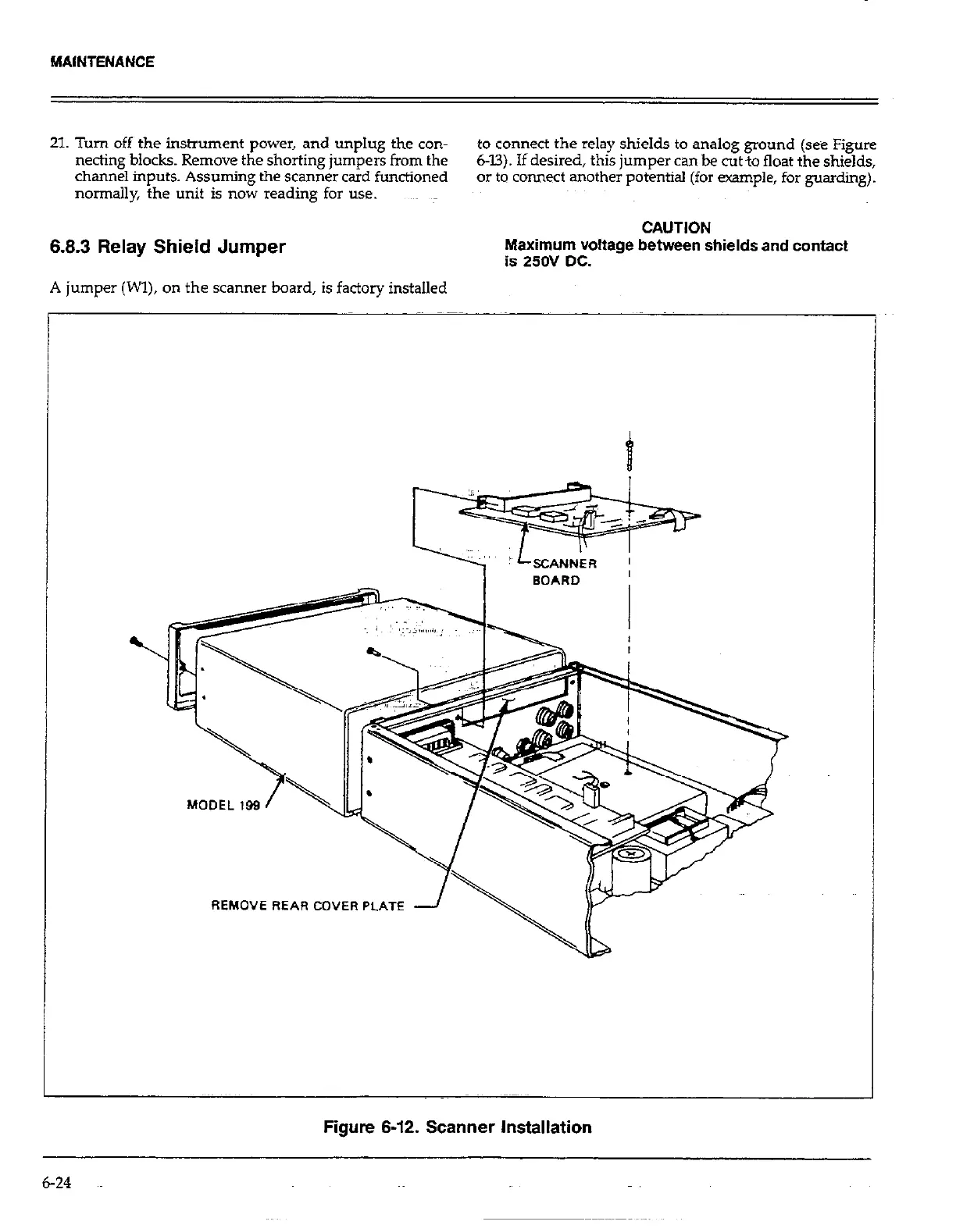
REMOVE REAR COVER PLATE
Figure 6-12. Scanner Installation
6-24
 Loading...