MAINTENANCE
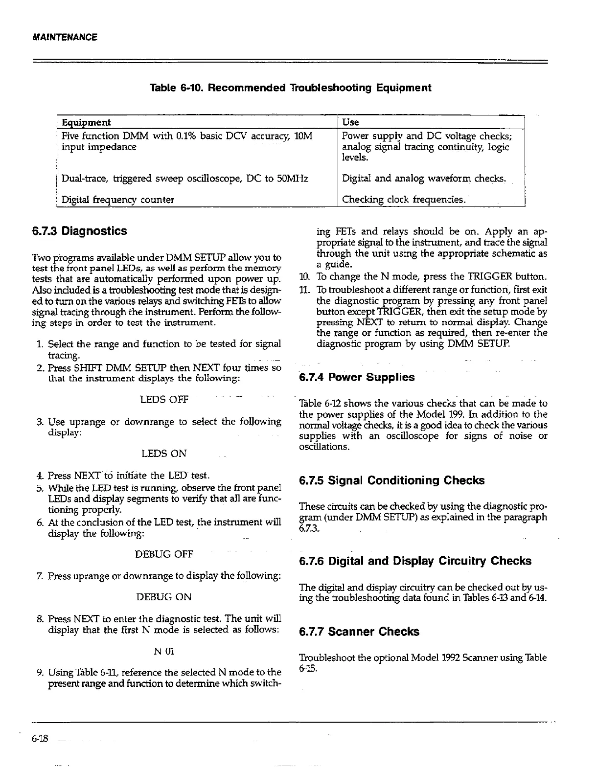
Table 6-10. Recommended Troubleshooting Equipment
Equipment
Five function DMM with 0.1% basic DCV accuracy, 10M
input impedance
Dual-trace, triggered sweep oscilloscope, DC to 50MHz
Digital frequency counter
6.7.3 Diagnostics
Two p?ograms available under DMM SETUP allow you to
test the front panel LEDs, as well as perform the memory
tests that are automatically performed upon power up.
Also included~is a truubleshooting test mode that is design-
ed to turn on the various relays and switching FETs to allow
signal tracing through the instrument. Perform the follow-
ing steps in order to test the instrument.
1. Select the range and function to be tested for signal
tracing.
2. Press SHm DMM SETUP then NEXT four times so
that the instrument displays the following:
LEDS OFF
3. Use uprange or downrange to select the following
display:
LEDS ON
4. P&s NEXT t0 initiate the LED test.
5. While the LED test is running, observe the front panel
LEDs and display segments to verify that all are func-
tioning properly.
6. At the conclusion of the LED test, the instrument will
display the following:
DEBUG OFF
7. Press uprange or downrange to display the following:
DEBUG ON
8. Press NEXT to enter the diagnostic test. The unit will
display that the first N mode is selected as follows:
N 01
9. Using Table 6-Q reference the selected N mode to the
present range and function to determine which switch-
Use
Power supply and DC voltage checks;
analog signal tracing co#jnuity, logic
levels.
Digital and analog waveform che&.
Checking clock frequencies.
ing FETs and relays should be on. Apply an ap-
propriate signal to the instrument, and trace the signal
through the unit using the appropriate schematic as
a guide.
10. To change the N mode, press the TRIGGER button.
11. To troubleshoot a different range or function, fmt exit
the diagnostjc-program by pressing any front panel
button except TRIGGER, then exit the setup mode by
pressing NEXT to return to normal display. Change
the range or function as required, then reenter the
diagnostic program by using DMM SETUP.
6.7.4 Power Supplies
Table 6-12 shows the various checks that can be made to
the power supplies of the Model 199. In addition to the
normal voltage checks, it is a good idea to check the various
supplies with an oscilloscope for signs oft noise or
oscillations.
6.7.5 Signal Conditioning Checks
These circuits can be checked by using the diagnostic pro-
gram (under DMM SETUP) as explained in the paragraph
6.7.3.,
6.7.6 Digital and Display Circuitry Checks
The digital and display circuitry can be checked out by us-
ing the troubleshooting data found in Tables 6X3 and 6-14.
6.7.7 Scanner Checks
Troubleshoot the optional Model 1992 Scanner using Table
6-E
 Loading...