IEEE-488 PROGRAMMING
T (Talker)-The ability of the Model 199 to send data over
the bus to other devices is defined by the T function. Model
199 talker capabilities exist only after the instrument has
been addressed to talk.
L (Listener)-The L function defines the ability of the
Model 199 to receive device-dependent data over the bus.
Listener capabilities atist only after the instrument has
been addressed to listen.
SR (Service Request)-The SR function defines the ability
of the Model 199 to request service from the controller.
RL (Remote-Local)-The RL function defmes the capabili-
ty of the Model 199 to be placed in the remote OI local
modes.
PP (Parallel Poll)-l’he Model 199 does not have parallel
polling capabilities.
DC (Device Clear)-The DC function defmes the ability bf
the Model 199 to be cleared (initialized).
DT (Device Trigger)-The ability for the Model 199 to have
its readings triggered~is defined by the DT function.
C (Controller)-The Model 199 does not have controller
capabilities.
TE (Extended Talker)-The Model 199 does not have ex-
tended talker capabilities.
LE (Extended Listener)-The Model 199 does not have ex-
tended listener capabilities.
E (Bus Driver Type)-The Model 199 has open-collector bus
drivers.
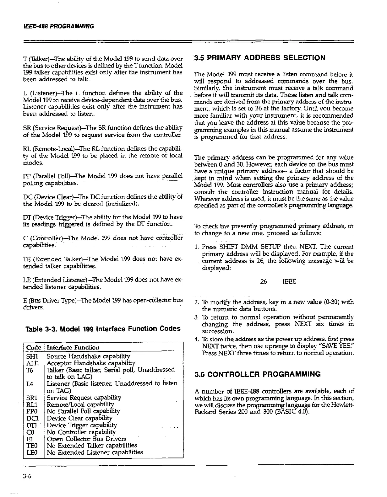
Listener (Basic listener, Unaddressed to listen
on TAG)
SRl
Service Request capability
RLl
Remote/Local capability
PPO
No Parallel Poll capability
E:
Device Clear capability
Device Trigger capability
co
No Controller capability
Open Collector Bus Drivers
No Extended Talker capabilities
No Extended Listener capabilities
$0
LEO
Table 3-3. Model 199 Interface Function Codes
Talker (Basic talker, Serial poll, Unaddressed
3.5 PRIMARY ADDRESS SELECTION
The Model 199 must receive a listen command before it
will respond to addressed commands over the bus.
Siiarly, the instrument must receive a talk command
before it will transmit its data. These listen and talk com-
mands are derived from the primary address of the instru-
ment, which is set to 26 at the factory. Until you become
more familiar with your instrument, it is recommended
that you leave the address at this value because the pro-
gramming examples in this manual assume the instrument
is programmed for that address.
The primary address can be programmed for any value
between 0 and 30. However, each device on the bus must
have a unique primary address-- a factor that should be
kept in mind when setting the primary address of the
Model 199. Most connolIers also use a primary address;
consult the controller instnxtion manual for details.
Whatever address is used, it must be the same as the value
specified as part of the contmllefs progtamming language.
To check the presently programmed primary address, OI
to change to a new one, proceed as follows:
1. Press SHE3 DMM SETUP then NEXT. The current
primary address will be displayed. For example, if the
current address is 26, the following message will be
displayed:
26 IEEE
2. To modify the address, key in a new value (O-30) with
the numeric data buttons.
3. To return to normal operation without permanently
changing the address, press NEXT six times in
succession.
4. To store the address as the power up address, first press
NEXT twice, then use uprange to display “SAVE YES.”
Press NEXT three times to return to normal operation.
3.6 CONTROLLER PROGRAMMING
A number of IEEE=488 controllers aTe available, each of
which has its own progra
mming language. In this section,
we will discuss the programming language for the Hewlett-
Packard Series 200 and 300 (BASIC 4.0).
3-6
 Loading...