PRINCIPLES OF OPERATION
5.3.3 -2.8V Reference Source
Voltage~and current measurements are based on compar-
ing the unknown signal with an internal -2.8V reference
voltage source. During each measurement cycle, the
unknown signal is sampled and then compared with
signal common and the -2.8V reference values.
VR2 provides a highly stable -6.4V reference,~ while UU
and R66 provide a constant current to minimize zener
voltage variations. Rb8 and R69 divide down the -6.4V
value to the final -2.8V reference voltage.
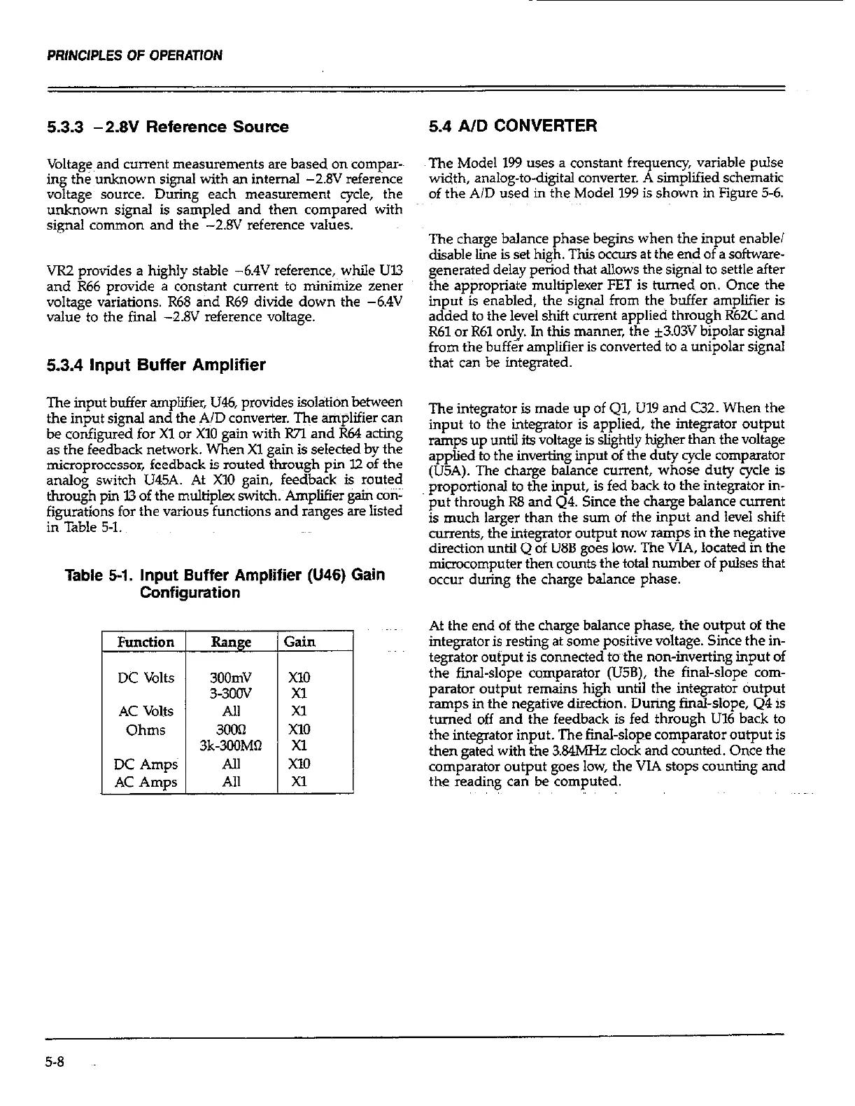
5.3.4 Input Buffer Amplifier
The input buffer amplifier, U46, provides isolation between
the input signal and the AID converter. The amplifier can
be configured for Xl or X10 gain with R7I and R64 acting
as the feedback network. When Xl gain is selected by the
microprocessor, feedback is routed through pin l2 of the
analog switch U45A. At X10 gain, feedback is routed
through pin I3 of the multiplex witch. Amplifier gain con-
figurations for the various functions and ranges are listed
in Table 5-1.
Table 5-1. Input Buffer Amplifier (U46) Gain
Configuration
Function
DC Volts
AC Volts
Ohms
DC Amps
AC Amps
Range
3oomv
33OOV
AlI
3003
3k-3OOMO
All
All
Gain
5.4 AID CONVERTER
The Model 199 uses a constant frequency, variable pulse
width, analog-to-digital converter. A simplified schematic
of the A/D used in the Model 199 is shown in Figure 5-6.
The charge balance phase begins when the input enable/
disable line is set high. This occurs at the end of a software-
generated delay period that allows the signal to settle after
the appropriate multiplexer FET is turned on Once the
input is enabled, the signal from then buffer amplifier is
added to the level shit current applied through R62C and
R61 or R61 only. In this manner, the *303V bipolar signal
from the buffer amplifier is converted to a unipolar signal
that can be integrated.
The integrator is made up of Ql, Ill9 and C32. When the
input to the integrator is applied, the integrator output
ramps up until its voltage is slightly higher than the voltage
applied to the inverting input of the duty cycle comparator
(U5A). The charge balance current, whose duty cycle is
proportional to the input, is fed back to the integrator in-
put through R8 and 44. Since the charge balance current
is much larger than the sum of the input and level shit
currents, the integrator output now ramps in the negative
direction until Q of U8B goes low. The VIA, located in the
microcomputer then counts the total number of pulses that
occur during the charge balance phase.
At the end of the charge balance phase, the output of the
integrator is resting at some positive voltage. Since the in-
tegrator output is connected mthe non-inverting input of
the final-slope comparator (U5B), the final-slope com-
parator output remains high until the integrator output
ramps in the negative direction. During final-slope, Q4 is
turned off and the feedback is fed through U16 back to
the integrator input. The final-slope comparator output is
then gated with the 3.84MHz clock and counted. Once the
comparator output goes low, the VIA stops counting and
the reading can be computed.
5-8
 Loading...