2.6.4 DC Voltage Measurements
with higher voltages are significant in microvolt signals.
The Model 199 reads only the sipnal received at its inout:
The Model 199 can be used to make DC voltage measure-
therefore, it is import& that-this signal be prop’erl;
ments in the range of *lpV to +30W.-Use the folIowing
tiansmitted from the source. Se following paragraphs in-
procedures to make DC voltage measurements.
dicate factors which affect accuracy, including thermal ernfs
and stray pick-up.-
CAUTION
The maximum input voltage between the HI and
Shielding-AC voltages which are extremely large com- ,tages which are extremely Iage com-
LO terminals is 42% peak or 300V RMS
pared with the DC signal may erroneously produce a DC : tne vc‘ signal may erroneously produce a DC
whichever is less. Exceeding this value may
output. Therefore, if there is AC interference, the circuit wefore, if there is AC interference, the circuit
cause instrument damage.
should be shielded with the shield connected to the Model -L’-‘J-J, with the shield connected to the Model
199 input LO (particularly for low-level sources). Improper
N ~par&ularly for low-level sources). Improper
shielding can cause the Model 199 to behave in one or more
sn cause the Model 199 to behave in one or more
1. Select the DC volts function by pressings the VOLTS
of the following ways: wing ways:
__ - __ -
button.
hntton
2. Select a range consistent with the expected voltage or
1. Unexpected offset voltages. d offset voltages.
use autorange.
2 Inconsistent readings between ranges,
-‘ ----lings between ranges,
3. Select the front or rear panel input terminals with the
3. Sudden shifts in reading. um m reading.
INPUT switch.
NnTF
._-.-
To minimize pick-up, keep the voltage source and the
Model 199 away from strong AC rn@~etic sources. The
The 3OOmV DC range requires zero to be-set in
voltage induced due to magnetic flux ii proportional to the
order to achieve rated accuracy. The zero correc-
area of the loop formed by the input leads. Therefore,
tion procedure can be found in paragraph 26.2.
minimize the loop area of the input leads and connect each
Signal at otily one point.
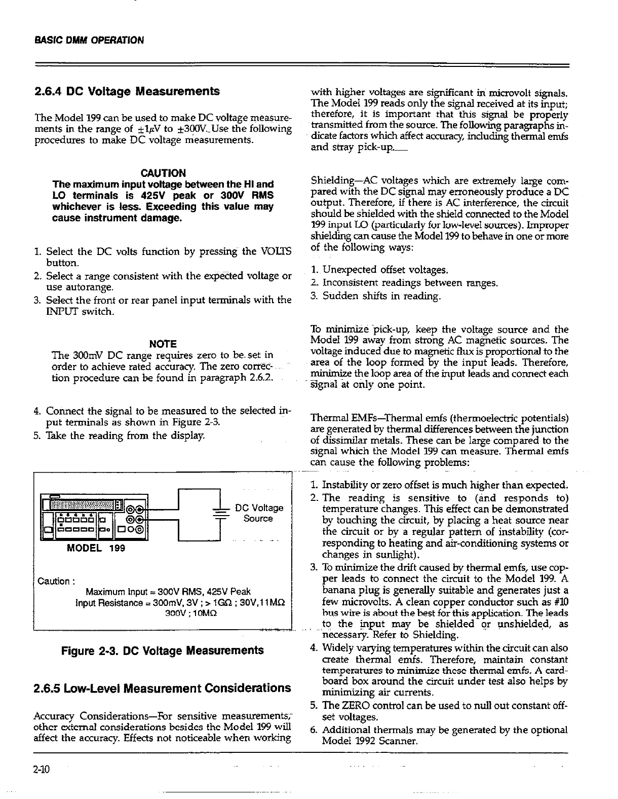
g. Cofinect the signal to be measured to the selected in-
put terminals as shown in Figure 2-3.
5. Take the reading from the display.
DC Voltage
source
MODEL 199
I
Caution :
Maximum Input = 300V RMS, 425V Peak
Input Resistance = 300rnV, 3V ; > lCX2 ; 3OV,llMQ
300V : 1 OMR
Thermal EMFs-Thermal emfs (thermoelecttic potentials)
are generated by thermal differences between the junction
of dissimilar metals. These can be large compared to the
signal which the Model 199 can measure. Thermal emfs
can cause the following problems:
1. Instability or zero offset is much higher than expected.
2. The reading is sensitive to (and responds to)
temperature changes. This effect can be demonstrated
by touching the circuit, by placing a heat source near
the circuit or by a regular pattern of instability (cor-
responding to heating and air-condition@ systems or
changes in sunlight).~
3. To minimize the drift caused by thermal emfs, use cop-
per leads to connect the circuit to the Model 199. A
banana plug is generally suitable and generates just a
few microvolts. ~A clean copper conductor such as #lO
bus wire is about the best for this aonlication. The leads
. .,-,. .._~~
to the *put may Abe shiclded’ir unshielded, as
” “‘n&essary. Refer to Shielding.
Figure 2-3. DC Voltage Measurements
4. Widely varying temperatures-w&ii the circuit can also
create thermal emfs. Therefore, maintain constant
temperatures to minimize these thermal emfs. A card-
2.6.5 Low-Level Measurement Considerations
board box around the circuit under test also helps by
minimizing air currents.
5. The ZERO control can be used to null out constant off-
Accuracy Considerations-For sensitive measurements;
other external considerations besides the Model 199 will
set voltages.
affect the accuracy. Effects not noticeable when working
6. Additional thermals may be generated by the optional
Model 1992 Scanner.
Z-10
 Loading...