IEEE-488 PROGRAMWNG
3.3 BUS CONNECTIONS
The Model 199 is intended to be connected to the IEEE48
bus through a cable equipped with standard IEEE-488 con-
nectors, an example of which is shown in Figure 3-2. The
connector is designed to be stacked to allow a number of
parallel connections at one instrument. Two scraVs are
located on each connector to ensure that connections re-
main secure. Current standards call for metric threads,
which are identified with dark colored screws. Earlier ver-
sions had different screws, which were silver colored. Do
not attempt to use these type of connectors on the Model
199, which is designed for metric threads.
Figure 3-2. IEEE-488 Connector
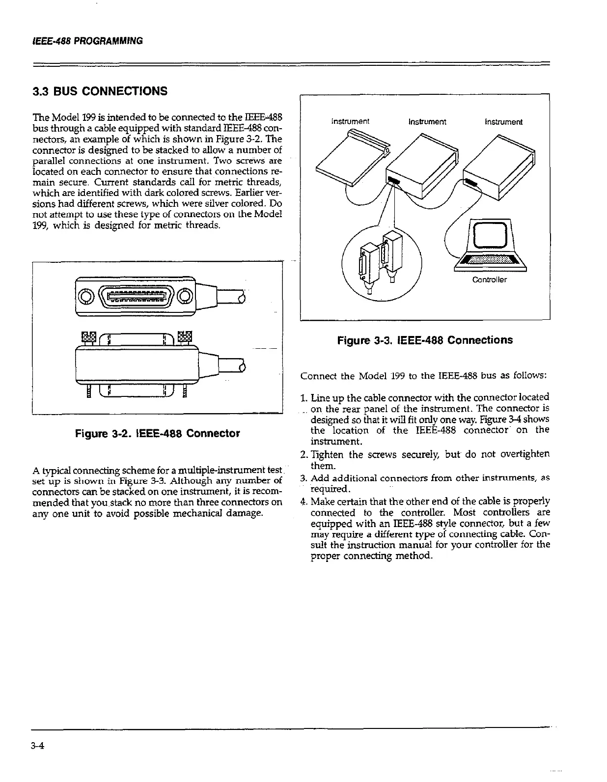
Figure 3-3. IEEE-488 Connections
Connect the Model 199 to the IEEE-488 bus as follows:
1. Lie up the cable connector with the connector located
on the rear panel of the instrument. The connector is
designed so that it will fit only one way. Figure 34 shows
the location of the IEEE-488 c&nectcW on the
instrument.
2.Tighten the screws securely, butt do not overtighten
_.
A typical connecting scheme for a multiple-instrument test:
met-n.
set up is shown in Figure 3-3. Although any number of
3. Add additional connectors from other instruments, as
connectors can be stacked on one instnunent, it is recom-
~~ required.
mended that you~stack no more than three connectors on
4. Make certain that theother end of the cable is properly
any one unit to avoid possible mechanical damage.
connected to the controller. Most controllers are
equipped with an IEEE-488 style connector, but a few
may requtie a different type of connecting cable. Con-
sult the instruction manual for your controller for the
proper connecting method.
3-4
 Loading...