MAINTENANCE
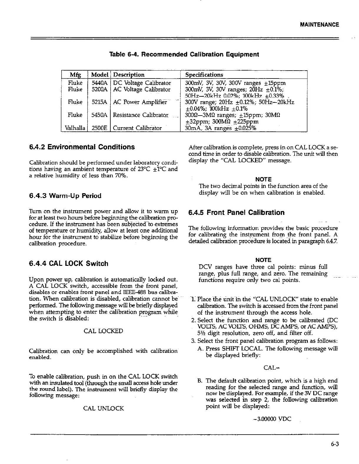
Table 6-4. Recommended Calibration Equipment
Mfg Model Description
Fluke
5440A DC Voltage Calibrator
Fluke 52OOA AC Voltage Calit+or
Specifications
3OOmV, 3V, 3OV, 300V ranges *l5ppm
33OmV, 3% 3OV ranges; 20Hz 20.1%;
50Hz-20kHz 0.02%: 1OOkH.z +0.33%
/ Fluke 1 52l5A 1 AC Power Atiplifiier ;/ 3oOV range; 20Hz iO.1246; 50i?z-2dkHz
/
&0.04%; iOOkHz +O.l%
Fluke
5450A Resistance Calibrator 3000-3MQ ranges; +l5ppm; 30MQ
+32ppm; 3OOMR @5ppm
Valhalla 2500E Current Calibrator 30mA,~3A ranges +O.OU%
6.4.2 Environmental Conditions
Calibration should be performed under laboratory condi-
tions having an ambient temperature of 23°C +l’C and
a relative humidity of less than 70%.
6.4.3 Warm-Up Period
Turn on the instrument power and allow it to warm up
for at least two hours before beginning the calibration pro-
cedure. If the instrument has been subjected~to &r&es
of temperature or humidity, allow at least one additional
hour for the instrument to stabilize before beginning the
calibration procedure.
6.4.4 CAL LOCK Switch
Upon power up, calibration is automatically locked out.
A CAL LOCK switch, accessible from the front panel,
disables or enables front panel and IEEE488 bus calibra-
tion. When calibration is disabled, calibration cannot be
performed. The following. message will be briefly displayed
when attempting to enter the calibration p+gram while
the switch is disabled:
CAL LOCKED
Calibration can only be accomplished with calibration
enabled.
To enable calibration, push in on the CAL LOCK switch
with an indated tool (through the smaU access hole under
the round label). The instrument will briefly display the
following message:
CAL UNLOCK
After calibration is complete, press in on CAL LOCK a se-
cond time in order to disable calibration. The unit will then
display the “CAL LOCKED” message.
NOTE
The two detiinal points in the function area of the
display will be on when calibration is enabled.
6.4.5 Front Panel Calibration
The following information provides the basic procedure
for calibrating the instrument from ~the front panel. A
detailed calibration procedure is located in paragraph 6.4.7
NOTE NOTE
DCV ranges have three cal points: minus full DCV ranges have three cal points: minus full
range, plus full range, and zero. The remaining range, plus full range, and zero. The remaining
functi&s require only two cal points. functi&s require only two cal points.
1. Place the tinit fin the “CAL UNLOCK” state to enable
calibration. The switch is accessed from the front panel
of the instrument through the access hole.
2. Select the function and range to be calibrated (DC
VOLTS, AC VOLTS, OHMS, DC AMPS, or AC AMPS),
5% digit resolution, zero off, and filter off.
3. Select the front panel calibration program as follows:
A. Press SHW LOCAL. The following message will
be displayed briefly:
CAL=
B. The default calibration point, which is a high end
reading for the selected range and function, will
now be displayed. For example, if the 3V DC range
was selected in step 2, the following calibration
point will be displayed:
6-3
 Loading...