Table 4-3. Limits for TRMS AC Volts Verification
199 Applied
Allowable Readings WC to ‘28Tl
ACV Range AC Voltage ZOHZ 5oHz 200Hz lOkHz 1OOkHz
3OOmv 29O.OOOmv 284.100 288.885
289.365 289.365 283.900
29&l 29k5 Z&5 29&5 29&W
3 v 2.90000V 2.84lOO 2.88885
2.89365 2.89365 2.85350
2.9&Q Z.%l5
2.600635 2.&35 2.94650 to
30 v 29.MxMv 28.4100 28.8885
28.9365 28.9365 28.5330
29:090 29%5
29.:35 29.k.5 29.4650 to
3ooV 29O.OOOV 284.100 288.885
289.365 289.365 *
to to to to
295.900 291.lS
290.635 290.635
*Do not apply 290V at 1OOkHz to the input. This exceeds the V*& limit of the
instrument. Maximum TRh4S AC volt input at 1CHlkHz is 1WV. On the SHIV range,
allowable readings with lOOV @ lOOkI& applied to the input are 98.200 to lO’L800.
See par+aph 2.6.7 for clarification of the V-Hz specification.
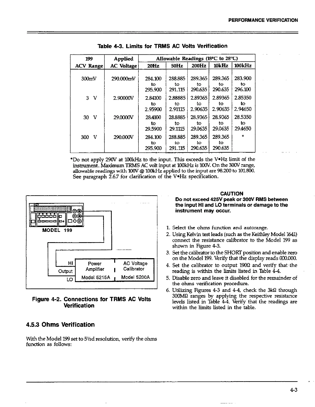
Figure 4-2. Connections for TRMS AC Volts
Verification
4.5.3 Ohms Verification
With the Model 199 set to 5%d resolution, verify the ohms
function as follows:
CAUTION
Do not exceed 425V peak or 300V RMS between
the input HI and LO terminals or damage to the
instrument may occur.
1. Select the ohms function and autorange.
2. Using Kelvin test leads (such as the Keithley Model 1641)
connect the resistance calibrator to the Model 199 as
shown in Figure 43.
3. Set the calibrator to the SHORT position and enable zero
on the Model 199. Verify that the display reads ooO.000
4. Set the calibrator to output 1900 and verify that~ the
reading is within the limits listed in Table 4-4.
5. Disable zero and leave it disabled for the remainder of
the ohms verification procedure.
6. Utilizing Figures 43 “d 44, check the 3kX7 through
3CilMQ ranges by applying the respective resistance
levels listed in Table 44. Verify~ that the readings are
within the limits listed in the table.
,,
4-3
 Loading...