BASIC DMM OPERATION
2.4.1 Connectors and Terminals
2.4.4 Scanner Card Sloth
El
Input terminals-The rear panel VOLTS OHMS and
OHMS SENSE terminals perform the same fufic-
tions as the equivalent front panel terminals.
Voltage and two-wire resistance measurements are
made using the VOm OHMS ~terminals, while
four-wire r&stance measurements are made using
both the OI-IMS SENSE eland VOLTS OHMS
termin&.
El
EXTERNAL TRIGGER INPUT--This BNC connec-
tor is used to apply negative-going. TlLconipatible
trigger pulses to take one or more readings depen-
dig on the selected trigger mode. See paragraph
2.9 for additional information.
q ~~
VOLTMETER COMPLETE OUTPUT-Thii BNC
output connector provides a lTLcompatible,
negative-going pulse when the Model 1% has com-
pleted a reading. It can be used to trigger other in-
struments, as discussed in paragraph 2.9.
The optional Model 1992 Scanner Card installs in this slot.
Refer to paragraphs 2.11 and 3.12 for scanner operation and
programming information. Section 6 contains scanner in-
stallation procedures.
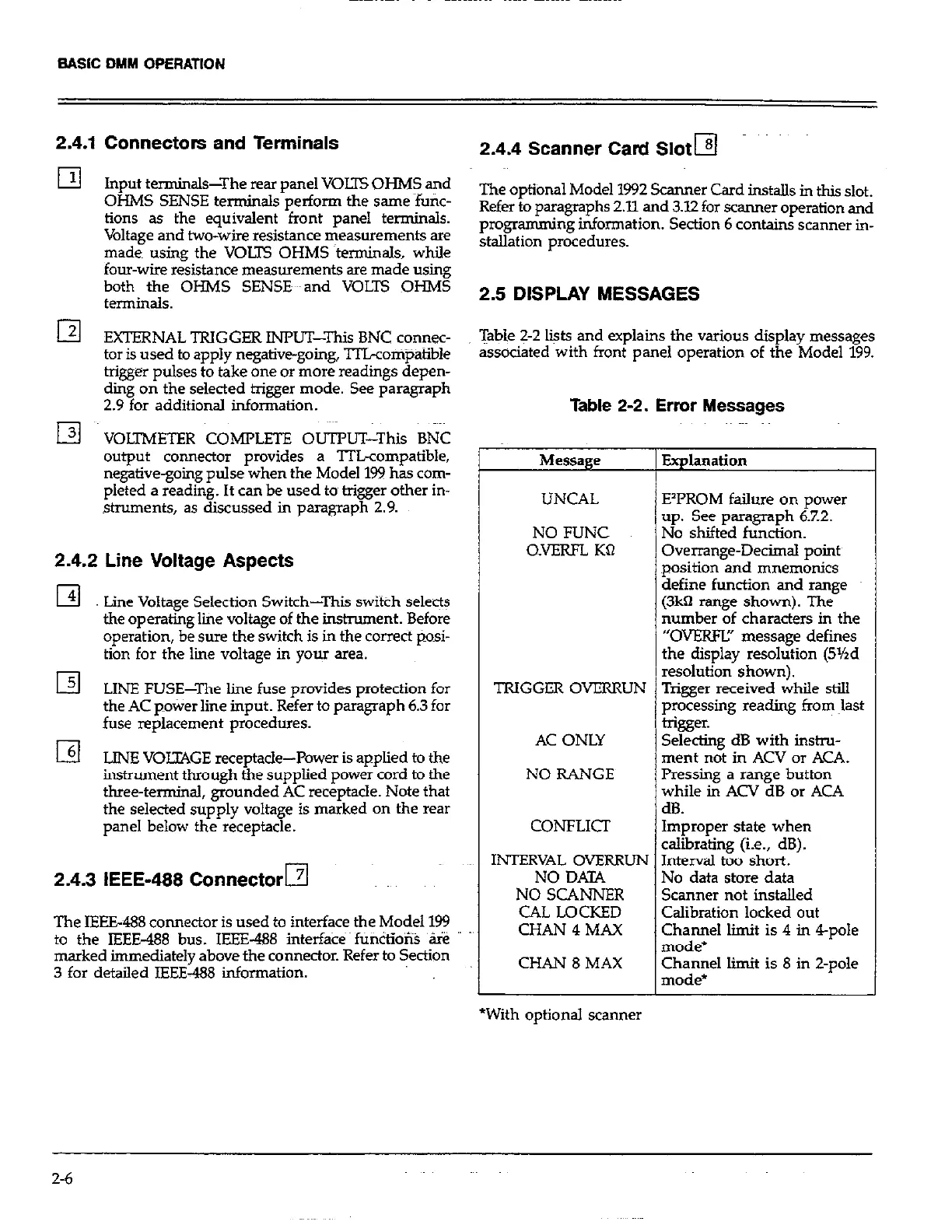
2.5 DISPLAY MESSAGES
Table 2-2 liits and explains the various display messages
associated with front panel operation of the Model 199.
Table 2-2. Error Messages
Message
Explanation
UNCAL
NO FUNC
O.VERFL KQ
E’PROM failure on power
up. See paragraph 6.7.2.
No shifted function.
Overrange-Decimal pointy
position and mnemonics
define function and range
(3k0 range shown). The
number of characters in the
“OVEKW’ message defines
the display resolution (5%d
resolut~on~shown).
2.4.2 Line Voltage Aspects
El
Lme Voltage Selection Switch-This switch selects
the operating lie voltage of the instrument. Before
operation, be sure the switch is in the correct pOsi-
tion for the lie voltage in your area.
El LINE FUSE-The line fuse provides protection for
the AC pokier line input. Refer to paragraph 6.3 for
fuse replacement procedures.
I3
LINE VOLZ4GE receptacle-Power is applied to the
instrument through the supplied power cord to the
three-terminal, grounded AC receptacle. Note that
the selected supply voltage is marked on the rear
panel below the receptacle.
2.4.3 IEEE-488 Connector El
The IEEE488 connector is used to interface the Model 199
to the IEEE-488 bus. IEEE-488 interfa& fU&io% ‘s
marked immediately above the connector. Refer to Section
3 for detailed IEEE-488 information.
TRIGGER OVERRUN Trigger received while still
processing reading from last
trigger.
AC ONLY Selecting dB with instru-
ment not in ACV or ACA.
NO RANGE Pressing a range button
while in ACV dB or ACA
dB.
CONFLICT Improper state when
calibrating (i.e., dB).
INTERVAL OVERRUN Interval too short.
NO DATA
NO SCANNER
CAL LOCKED
CHAN 4 MAX
CHAN 8 MAX
No data store data
Scanner not installed
Calibration locked out
Channel limit is 4 in 4-pole
mode*
Channel limit is 8 in Z-pole
mode*
*With optional scanner
2-6
 Loading...