MAlNTENANCE
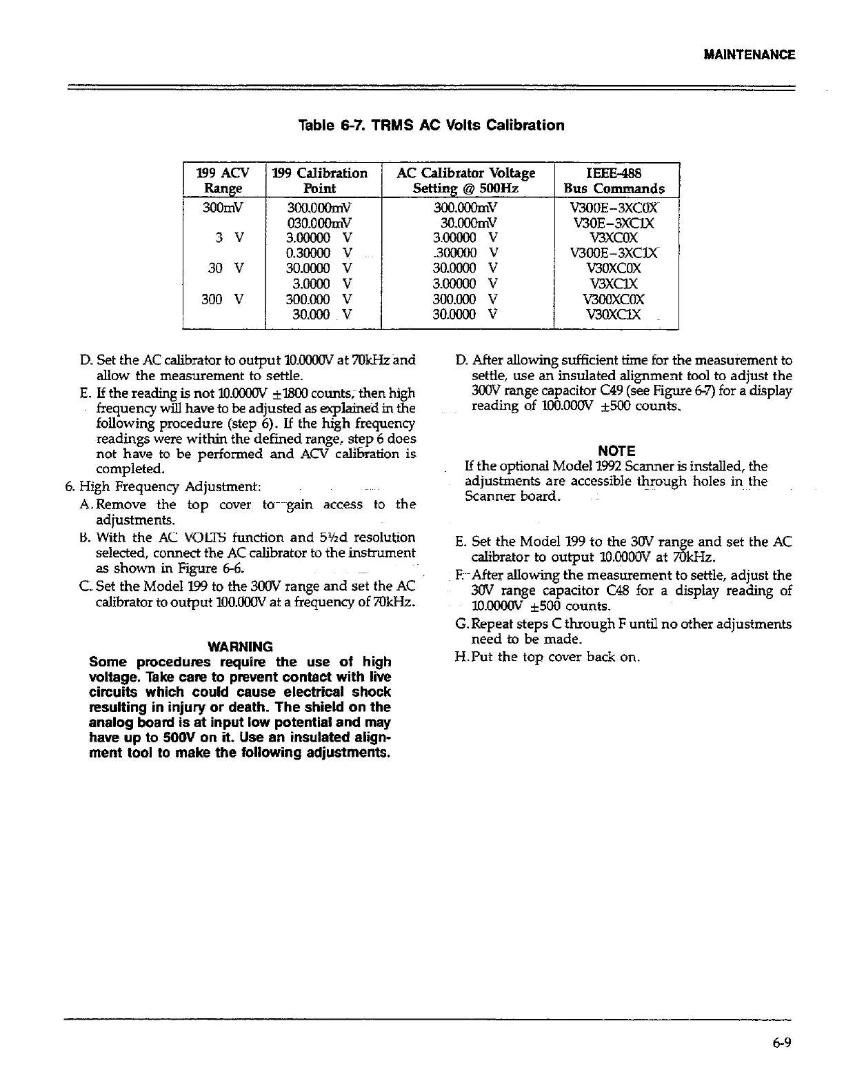
Table 6-7. TRMS AC Volts Calibration
199 Calibration
AC Calibrator Voltage
Point
setting @ 5ooHz
3oo.ooomv
3oo.ooomv
030.0oomv
3O.OOOmV
3.G6nlo v
3.00000 v
0.3rHIoo v
.3lxIooo v
3o.oooo v
30.m v
3.otnxl v
3.MxMo v
3oo.ooo v
3oo.ooo v
3o.ooo v
3o.ocHlo v
IEEE-488
Bus Commands
WOE-3XCOX
V3OE-3XClX
vxcox
V300E-3XClX
v3oxcox
V3XClX
v3ooxcox
v3oxclx
D. Set the AC calibrator to output lO.OOMlV at 7OkHzand
aIlow the measurement to settle.
E. lf the reading is not KKKKIV 11800 counts;then high
frequency will have to be adjusted as explained in the
following procedure (step 6). If the high frequency
readings were within the defined range, step 6 does
not have to be performed and ACV calibration is
completed.
6. High Frequency Adjustment:
A.Remove the top cover to~m~~gain access to the
adjustments.
B. With the AC VOLTS function and 5Yzd resolution
selected, connect the AC calibrator to the instrument
as shown in Figure 6-6.
CL Set the Model 199 to the 3oov range and set the AC
calibrator to output lOO.OCNV at a frequency of 7QkHz.
WARNING
Some procedures require the use of high
voltage. Take cam to prevent contact with live
circuits which could cause electrical shock
resulting in injury or death. The shield on the
analog board is at input low potential and may
have up to SOOV on it. Use an insulated align-
ment tool to make the following adjustments.
D. After allowing sufficient time for the measurement to
settle, use an insulated alignment tool to adjust the
3COV mnge capacitor C49 (see Figure 6-7) for a display
reading of 1OO.OOOV *500 counts.
NOTE
If the optional Model 1592 Scanner is installed, the
adjustments are accessible through holes in the
Scanner board.
E. Set the Model 199 to the 30V range and set the AC
calibrator to output 1O.OOOOV at 7OkHz.
FPAfter allowing the measurement to settle, adjust the
3OV range capacitor C48 for a display reading of
1o.ooooV f500 counts.
G. Repeat steps C through F until no other adjustments
need to be made.
H.l’ut the top cover back on.
6-9