PRINCIPLES OF OPERATION
On the 3OV range, the signal is applied to U26A. Because On the 3OOV range, the signal is applied to U26A. Because
analog switch U2lA is open on this range, aniplifier U26A
analog switch U2L4 is closed on this range, amplifier U2&4
has a feedback resistance of 118kD (R32) which results in
a gain factor of 1110. The divided signal is then muted
has a feedback resistance of ll8k0 0732) in parallel with
pkfi (R24), resulting in a gain factor of 11100. The divided
through analog switch UZlB and buffer U26B to the TRMS
signal is then routed through analog switch U21B and buf-
converter (U27).
fer U26B to the TRMS converter (U27).
r--------~------
input Conditioning
1
I !
------ _______________ ~_.
IEEE-M
Intelfaca
Display
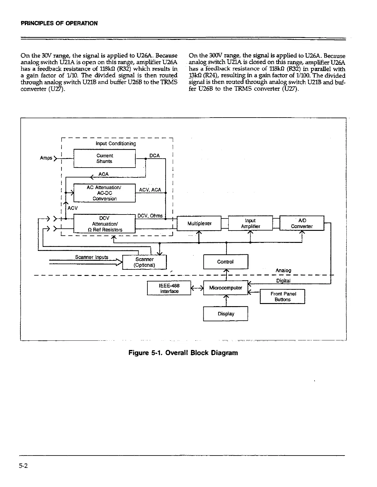
Figure 5-1. Overall Block Diagram
5-2
 Loading...