BASIC OYM OPERATION
2.8.5 Trigger Programming Examples
Example 1: Continuous with 3.5s~ intervals, between
readings.
1. Press SHIFi’ TRIG S.ETUP and then uprange or down-
range (if necessary) so the unit displays the following:
coNTINuous
2. Press NEXT twice to advance to the interval display
message.
3. Use uprange or downrange to choose select interval
(“SELECT ON”), if necessary, then press NEXL
4. Press: 0 0 3 5 0 0 in order to program a 3.5s~ interval.
5. Press NEXT to return to normal display.
6. Connect a time-varying signal to the instrument, and
select a function and range suitable for the applied
signal
7. Press TRIGGER to initiate readings. Note that the
display updates at a rate of once every 3% seconds, as
shown by the following decimal point.
Example 2: One-shot trigger mode with a one second hig-
ger delay.
1. Press SHJFI TRIG SETUP and then uprange or
downrange (if necessary) so the unit displays the
following:
ONE SHOT
2. Press NEXT to advance to the delay time selection.
3. Press: 0 0 1 0 0 0 to program a one second delay.
4. Press NEXT to return to normal display.
5. Connect a time-varying signal, and select an appropriate
range and function.
6. Press TRIGGER to initiate a single reading. Note that
the display updates once after a delay of approximately
one second.
7. Press TRIGGER a number of times, and note that one
reading per trigger is processed with a one second in-
terval between triggers and readings. The trigger~status
LED (flashing decimal point) indicates the display
update.
2.9 EXTERNAL TRIGGERING
The Model 199 has two external BNC connectors on the
rear panel associated with instrument triggering. The EX-
TERNAL TRIGGER INPUT connector allows the instru-
ment to be triggered by other devices, while the METER
COMPLETES OUTPUT connector allows the instrument to
trigger other devices.
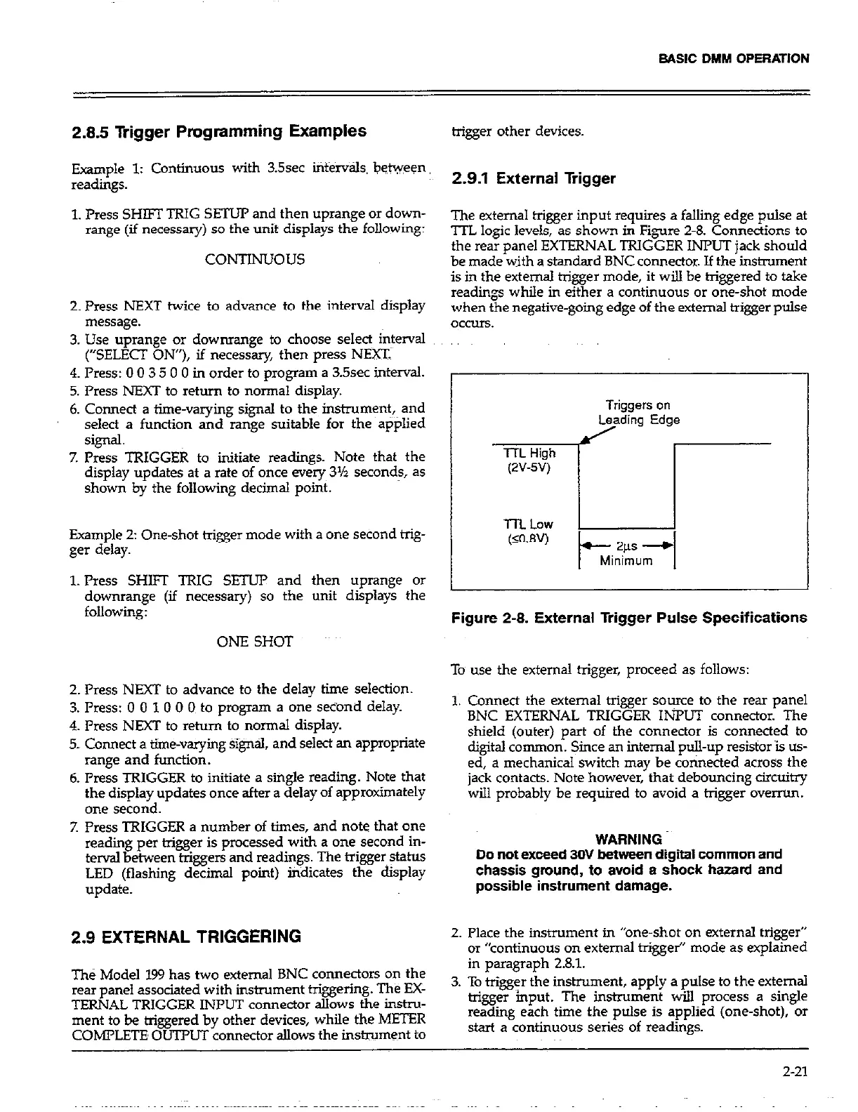
2.9.1 External liigger
The external trigger input requires a falling edge pulse at
TTL logic levels, as shown in Figure 2-8. Connections to
the rear panel EXTERNAL TRIGGER INPUT jack should
be made w~ith a standard BNC connector. If the instrument
is in the external trigger mode, it will be triggered to take
readings while in either a continuous or one-shot mode
when the negative-going edge of the external trigger pulse
CICCUIS.
,.
Triggers on
r(- Edgi
Figure 2-8. External Trigger Pulse Specifications
To use the external trigger, proceed as follows:
1. Connect the external trigger source to the rear panel
BNC EXTERNAL TRIGGER INPUT connector. The
shield (outer) part of the connector is connected to
digital com.mon. Since an internal pull-up resistor is us-
ed, a mechanical switch may be connected across the
jack contacts. Note however, that debouncing circuitry
will probably be required to avoid a trigger overrun.
WARNING
Do not exceed 3llV between digital common and
chassis ground, to avoid a shock hazard and
possible instrument damage.
2. Place the instrument in “one-shot on external trigger”
or “continuous on external trigger” mode as explained
in paragraph 2.8.1.
3. To trigger the instrument, apply a pulse to the external
trigger input. The instrument will process a single
reading each time the pulse is applied (one-shot), or
start a continuous series of readings.
2-21