BASIC DMM OPERATION
In order to perform the gain tests, the following general
To deterr@ne bandwidth, we can use the commonly-used
procedure should be followed.
-3dB points in frequency response. The dB~function of the
Model 199 simplifies this task a great deal.
1. Ci%nect the epuipnient together, as shown in Figure
2-Z
2. Assuming that AC gain is to be tested, place the Model
199 in the ACV function, and select a range high
enough to measure the expected output voltages.
3. Press SHIFT TRIG SETLJl? and select the one-shot trig-
eer mode, then oroaram a one-second delav. Return
& non&displa$ af& programming the tri&er mode
and delay.
4. P&s SHIFT SCAN SETUP, and program the 2-pole
mode.
5. Press NEXT, and select the STEP scan mode with
uprange or downrange.
6. Press NEXT, and turn on the ratio mode by using
uprange or downrange.
7. Press NEXT to exit the scanner setup mode.
8. Press SCANNER, and select a channel limit of 8.
9. If you wish to store the amplifier gain data, press
SHIFT STORE and select a reading size of 8. Press
NEXT to return to normal display.
10. Set the signal generator to the desired output frequency
(<3OOkHz) and amplitude for the gain test.
11. Press TRIGGER to initiate the scan. With the first trig-
ger, the instrument will take amplifier input voltage
reading on channel 1 and then store that reading as
the ratio reference value.
12. Press TRIGGER to advance to channel 2. At this point,
the instrument will display the ratio of channel 2 to
channel 1, in other words, the-gain of amplifier Al. To
display the gains of the remaining amplifiers, press
TRIGGER and note the displayed ratio for each
channel.
l3. If data store was enabled in step 9, press SHK
RECALL to review the gain data. Select~~a location of
1, then press NEXT to view the data, which will be the
absolute input voltage value. Press uprange to review
channel 2 through 8 data, which will show the gain
values of the respective amplifiers.
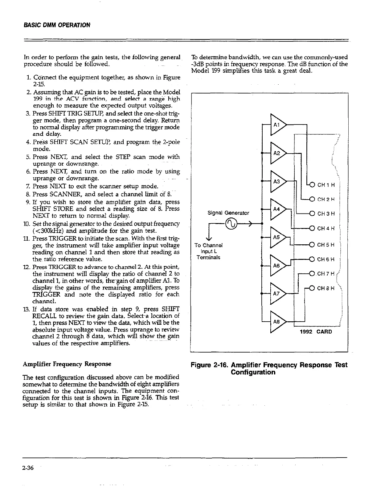
Amplifier Frequency Response
Figure 2-16. Amplifier Frequency Response Test
The test configuration discussed above can be modified
Configuration
somewhat to determine the bandwidth of eight amplifiers
connected to the channel inputs. The equipment con-
figurafion for this test is shown in Figure 2-16. This test
setup is similar to that shown in Figure 2-15.
Signal Generator
To Channel
Input L
Terminals
2-36
 Loading...