Front Panel Operation
3-77
For example, assume that a Model 2001 is connected to two
Model 7001 Switch Systems for semi-synchronous opera-
tion, as shown in Figure 3-37. All three instruments are pro-
grammed to use trigger line #1. The two Model 7001s have
relay settling times of 10msec and 50msec, respectively. The
Model 2001 is designated as the trigger control source and
the two Model 7001 units as trigger control acceptors.
Assume that the Model 2001 initially performs a
measurement. After the reading is done, the Model 2001
drives the trigger line low. The negative-going edge triggers
both Model 7001s to close a channel. While the Model 7001s
are in the process of closing a channel, they hold the trigger
line low. Ten milliseconds after switch closure, the first
Model 7001 releases the trigger line. However, the second
Model 7001 continues to hold the line low since it is not
finished. Fifty milliseconds after switch closure, the second
Model 7001 releases the trigger line. The positive-going
edge triggers the Model 2001 to make a measurement and
subsequently pull the trigger line back down to close the next
channels. This process continues until all channels are
scanned and measured.
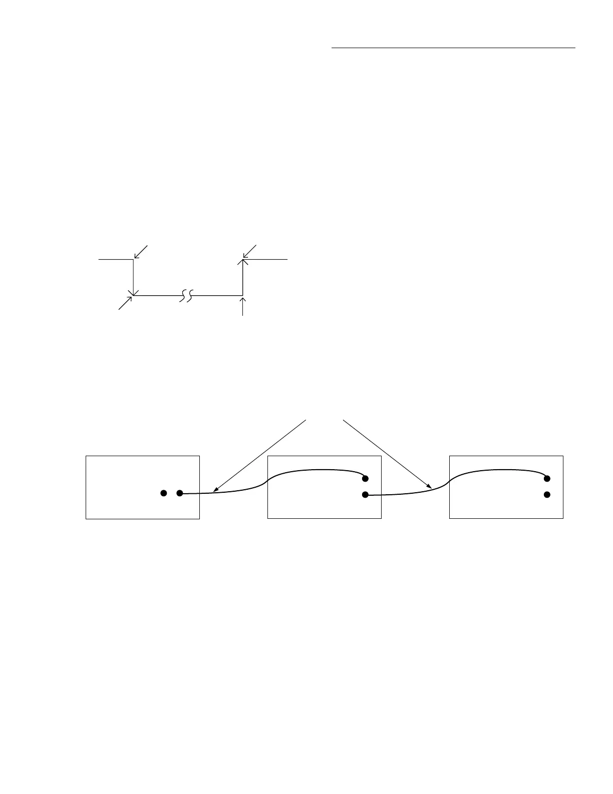
Figure 3-37
Typical semi-synchronous mode connections
Trigger
Link
7001 Switch System
Trigger Link
Cables (2)
(8501)
2001 Multimeter
IN
OUT
Trigger
Link
IN OUT
Line #1Line #1
Trigger
Link
7001 Switch System
IN
OUT
Semi-synchronous operation
In the Semi-synchronous Trigger Link mode, all triggering
(input and output) is controlled by a single line. When the
normally high (+5V) trigger line is pulled low (0V), a trigger
occurs on the negative-going edge. When the trigger line is
released, a trigger occurs on the positive-going edge (see
Figure 3-36). The advantage of this single line trigger is that
as long as one of the instruments in the system holds the line
low, the trigger is suppressed. In other words, the trigger
does not occur until all instruments in the system are ready.
igure 3-36
Semi-synchronous Trigger Link specifications
≈ +5V
Trigger on
negative-going
edge
Trigger on
positive-going
edge
Pulled low by
source instrument
Released by
acceptor instruments
0V

 Loading...


